Development and application of degradable polymer plastics |
Development and application of biodegradable polymer plastics, biodegradable plastics is a kind of new type with the function of degradation of polymer materials, in use process, it has to do with the same kind of common plastic with the corresponding health and relevant application performance, and after its complete function, the material can rapidly degraded in the natural environment conditions become easy to be given environment fragments or crushed, and with the passage of time further degradation become eventually oxidation products (CO2 and water), return to nature.
Based on the environmental pollution caused by plastic waste, as well as the demand of environmental protection and human needs, it is urgent to study degradable polymer materials. In a specific time and under certain environmental conditions, the chemical structure of biodegradable plastics will change. According to the reasons for the changes in its chemical structure, biodegradable plastics can be divided into two categories: biodegradable plastics and photodegradable plastics.
1. Degradation mechanism of degradable plastics
Generally speaking, degradable plastic refers to a kind of plastic that can be decomposed into small molecules through the action of microorganisms in soil or solar radiation.It must meet the requirements of the use of products and easy to process on the basis of the basis of biodegradable properties. The nature of the action of sunlight on polymer materials is the comprehensive effect of ultraviolet light in sunlight and oxygen in air, so it is also called photooxidation degradation. Take polyolefin as an example to explain the mechanism of photooxidation degradation. In essence, photooxidation causes chain breaking or crosslinking of polymers, and some oxygen-containing functional groups, such as carboxylic acids, peroxides, ketones and alcohols, are formed in this process. Catalyst residues in polymers and initiation of peroxide and carboxyl groups introduced during processing are the main sources of degradation.
Under the action of microorganisms (mainly fungi, bacteria or algae, etc.), polymers can be eroded or metabolized to cause changes in their chemical structure and decrease in molecular weight. The mechanism of action can be mainly divided into two situations :
(1) biophysical action. That is, after the erosion of plastic products by microorganisms, biological cells growth, promote the decomposition of polymers, ionization or proton, this physical action on the polymer caused mechanical damage, the high molecular weight of the polymer into oligomer fragments, so as to achieve the purpose of physical degradation.
(2) biochemical action -- direct action of enzymes. This situation is caused by the erosion of enzymes secreted by fungi or bacteria, which leads to the splitting or oxidative disintegration of plastics, and causes the splitting or oxidative degradation of insoluble polymers into water-soluble fragments, generating new small molecular compounds (CH4, CO2 and H2O) until the final decomposition.
There are generally two hypotheses about the mechanism of biodegradation of polymer materials that lead to biodegradation. The other is an invasive cut from the end of the chain. Therefore, the structural properties of materials, such as composition, main and side chain structure, size of end groups, and presence or absence of spatial steric resistance, are the key factors affecting their degradation performance. Among them, the main chain properties have a greater impact. If the main chain of the polymer contains bonds that are easily hydrolyzed, it will be easily biodegraded. Secondly, if the backbone is flexible, the degradation rate will be relatively fast, whereas if the backbone is rigid and orderly, the degradation rate will be slow.
The biodegradability of polymer materials is reduced by branching and crosslinking. For example, the introduction of hydrophobic groups at the end of polylactic acid (PLA) molecular chain can reduce the erosion rate at the initial stage of degradation. This is because in the original degradation process, PLA's erosion mainly depends on the structure of molecular chain end, and the addition of hydrophobic groups leads to the decline of its erosion rate. In addition, some researchers have studied the chemical structure of polymers and the relative molecular weight of materials that play an important role in their degradation.
2. Development of biodegradable plastics
The development direction of biodegradable plastics in the future can be as follows:
(1) biodegradable plastics were prepared by studying the biodegradation mechanism of degradable polymers, and the block copolymerization of biodegradable plastics with existing ordinary polymers, microbial polymers and natural polymers was studied and developed.
(2) to search for microorganisms that can produce polymer plastics, explore new polymers, analyze their synthesis mechanism in detail, improve their productivity through existing methods and genetic engineering methods, and study efficient methods of cultivating microorganisms.
(3) pay attention to the control of degradation rate, develop efficient degradation promoters and stabilizers to improve the biodegradation performance of degradable plastics, reduce their cost, and expand the market application.
(4) research and establish a unified definition of degradable plastics, enrich and improve the evaluation method of biodegradation, and further understand the degradation mechanism.


Development and application of biodegradable polymer plastics, biodegradable plastics is a kind of new type with the function of degradation of polymer materials, in use process, it has to do with the same kind of common plastic with the corresponding health and relevant application performance, and after its complete function, the material can rapidly degraded in the natural environment conditions become easy to be given environment fragments or crushed, and with the passage of time further degradation become eventually oxidation products (CO2 and water), return to nature.
Based on the environmental pollution caused by plastic waste, as well as the demand of environmental protection and human needs, it is urgent to study degradable polymer materials. In a specific time and under certain environmental conditions, the chemical structure of biodegradable plastics will change. According to the reasons for the changes in its chemical structure, biodegradable plastics can be divided into two categories: biodegradable plastics and photodegradable plastics.
1. Degradation mechanism of degradable plastics
Generally speaking, degradable plastic refers to a kind of plastic that can be decomposed into small molecules through the action of microorganisms in soil or solar radiation.It must meet the requirements of the use of products and easy to process on the basis of the basis of biodegradable properties. The nature of the action of sunlight on polymer materials is the comprehensive effect of ultraviolet light in sunlight and oxygen in air, so it is also called photooxidation degradation. Take polyolefin as an example to explain the mechanism of photooxidation degradation. In essence, photooxidation causes chain breaking or crosslinking of polymers, and some oxygen-containing functional groups, such as carboxylic acids, peroxides, ketones and alcohols, are formed in this process. Catalyst residues in polymers and initiation of peroxide and carboxyl groups introduced during processing are the main sources of degradation.
Under the action of microorganisms (mainly fungi, bacteria or algae, etc.), polymers can be eroded or metabolized to cause changes in their chemical structure and decrease in molecular weight. The mechanism of action can be mainly divided into two situations :
(1) biophysical action. That is, after the erosion of plastic products by microorganisms, biological cells growth, promote the decomposition of polymers, ionization or proton, this physical action on the polymer caused mechanical damage, the high molecular weight of the polymer into oligomer fragments, so as to achieve the purpose of physical degradation.
(2) biochemical action -- direct action of enzymes. This situation is caused by the erosion of enzymes secreted by fungi or bacteria, which leads to the splitting or oxidative disintegration of plastics, and causes the splitting or oxidative degradation of insoluble polymers into water-soluble fragments, generating new small molecular compounds (CH4, CO2 and H2O) until the final decomposition.
There are generally two hypotheses about the mechanism of biodegradation of polymer materials that lead to biodegradation. The other is an invasive cut from the end of the chain. Therefore, the structural properties of materials, such as composition, main and side chain structure, size of end groups, and presence or absence of spatial steric resistance, are the key factors affecting their degradation performance. Among them, the main chain properties have a greater impact. If the main chain of the polymer contains bonds that are easily hydrolyzed, it will be easily biodegraded. Secondly, if the backbone is flexible, the degradation rate will be relatively fast, whereas if the backbone is rigid and orderly, the degradation rate will be slow.
The biodegradability of polymer materials is reduced by branching and crosslinking. For example, the introduction of hydrophobic groups at the end of polylactic acid (PLA) molecular chain can reduce the erosion rate at the initial stage of degradation. This is because in the original degradation process, PLA's erosion mainly depends on the structure of molecular chain end, and the addition of hydrophobic groups leads to the decline of its erosion rate. In addition, some researchers have studied the chemical structure of polymers and the relative molecular weight of materials that play an important role in their degradation.
2. Development of biodegradable plastics
The development direction of biodegradable plastics in the future can be as follows:
(1) biodegradable plastics were prepared by studying the biodegradation mechanism of degradable polymers, and the block copolymerization of biodegradable plastics with existing ordinary polymers, microbial polymers and natural polymers was studied and developed.
(2) to search for microorganisms that can produce polymer plastics, explore new polymers, analyze their synthesis mechanism in detail, improve their productivity through existing methods and genetic engineering methods, and study efficient methods of cultivating microorganisms.
(3) pay attention to the control of degradation rate, develop efficient degradation promoters and stabilizers to improve the biodegradation performance of degradable plastics, reduce their cost, and expand the market application.
(4) research and establish a unified definition of degradable plastics, enrich and improve the evaluation method of biodegradation, and further understand the degradation mechanism.
|
Метки: plastics Polymer polymer materials polymer plastics |
Preparation of UHMWPE fiber |
UHMWPE, also known as high-strength high-modulus polyethylene, is currently one of the world's high-performance materials. Due to its comprehensive excellent properties such as corrosion resistance, wear resistance and low density, it is currently used in military protection materials, military mechanical materials, aerospace equipment and other military fields. The development of high-performance fiber is the foundation of a country's military equipment, and the advanced material can lead to the advanced military technology, which has become an important material foundation for the construction of a powerful modern country, and occupies a decisive position in the field of military materials worldwide.
1. Properties of UHMWPE fiber
UHMWPE fiber has excellent comprehensive properties, its relative density is small, can float on water. And UHMWPE fiber is the strongest fiber in the world at present. Compared with steel, UHMWPE fiber is more than ten times stronger than high-quality steel. In addition, UHMWPE fiber also has strong corrosion resistance, chemical resistance, wear resistance and other properties, comprehensive performance, UHMWPE fiber in many important fields in China play an important role.
1.1 Excellent mechanical properties
Compared with other high-performance fibers, UHMWPE fiber density is second only to conventional PE fiber and polypropylene fiber, and it is the optimal fiber material with the smallest density among bulletproof materials. It can reduce the weight of the material and achieve a lightweight effect while ensuring better bulletproof performance.
Compared with other properties, the tensile strength of UHMWPE is only second to that of PBO and polyaryl ester fiber, and it is only 0.1 different from that of polyaryl ester fiber. It can be seen that UHMWPE has excellent tensile strength.
Compared with other fibers, the initial modulus is only second to PBO and carbon fiber, which indicates that the fiber has a relatively good resistance to damage tension and is not prone to deformation. It is a kind of characteristic fiber with ultra-high specific strength and specific modulus, which plays an important role in bulletproof material.
1.2 Electrical insulation performance
UHMWPE fiber reflectance radar wave phenomenon is very few, with high conduction efficiency, enhance the dielectric constant of composite materials. Although the dielectric constant and loss value of polyethylene are the least among other materials, UHMWPE fiber has the performance that traditional polyethylene fiber can't reach, and it has better effect than general materials, so it is the preferred material for radar radome, with high quality and light effect.
1. 3 Weather resistance and wear resistance
UHMWPE fiber has excellent weather resistance and can keep the original high performance unchanged after a long time of illumination and harsh environment. At the same time, UHMWPE fiber has higher wear resistance and bending fatigue resistance than aramid fiber in high performance materials, so the wear resistance of this fiber is better than other high performance fibers. Due to its high wear resistance and easy processing performance, it has a good application prospect in the industrial field.
1. 4 Chemical corrosion resistance
The internal structure of UHMWPE fiber is relatively tight. It is precisely because of the high crystallinity and orientation of the molecular chain inside the fiber that the fiber has a strong chemical inertia. Therefore, under the acid and base state or the high and low temperature state, the fiber can keep its original performance unchanged for a long time, and still adapt to and play its value in the harsh environment.
1. 5 Self-lubricating properties
UHMWPE material compared with other engineering materials, UHMWPE material has very low friction factor, low friction factor makes the fiber itself better self-lubricating performance, it is the best material in plastic materials under the condition of no lubricant, so UHMWPE material is widely used in engineering, with very high use value. UHMWPE fiber is used in the operation of the machine, compared to the traditional steel and brass under the operation of the lubricant is better. Therefore, compared with ordinary materials, UHMWPE fiber not only saves the raw material cost, but also guarantees the excellent performance effect, so it has a higher use value.
2. Preparation method of UHMWPE fiber
2.1 Gel spinning method
There are many methods to prepare high performance UHMWPE fiber, but due to the reason of solvent itself, the preparation of UHMWPE fiber can not be achieved. Gel spinning is the most ideal method. Gel spinning method is different from general solution spinning or wet spinning, generally using high molecular weight polymers as raw material, made of semi dilute solution as spinning dope, flexible molecule chain solution to tangles in the semi dilute solution, and then spinning, crystallization, high tensile stretch chain, after extraction treatment to times the thermal stretching, which is made with high strength and high modulus fibers. The gel spinning method has the following basic characteristics: (1) ultra-high molecular weight polymer is used as raw material;(2) use semi-dilute solution as spinning stock; (3) hyperthermal stretching was carried out, and the tensile ratio was greater than 30.
2.2 Plasticizing melt spinning method
Melt spinning is made of polymer melt by melt spinning and extruding. Plasticized melt spinning is on the basis of melt spinning, adding an appropriate amount of diluent to the polymer melt for spinning, through the twin screw mixed solvent, and then extruded, soaked in the extraction agent, and then repeated stretching can finally get high strength and high modulus polyethylene fiber.
2.3 High pressure solid state extrusion method
The principle of extrusion forming is that granular solid solvent is added to the extruder, the material barrel containing solid solvent is heated to the melting temperature, so that the solid material is molten, the molten agent is transported to the head of the machine with a fixed shape, and then after cooling and shaping, the final product is solidified. High pressure solid extrusion method is on the basis of extrusion forming high pressure melting, forming solvent, then through the jet hole, and then high tensile, and finally get high molecular weight polyethylene.
2.4 Surface crystallization method
Due to the slow growth rate of fibrous crystal, this method is seldom used in the preparation of UHMWPE fiber.


UHMWPE, also known as high-strength high-modulus polyethylene, is currently one of the world's high-performance materials. Due to its comprehensive excellent properties such as corrosion resistance, wear resistance and low density, it is currently used in military protection materials, military mechanical materials, aerospace equipment and other military fields. The development of high-performance fiber is the foundation of a country's military equipment, and the advanced material can lead to the advanced military technology, which has become an important material foundation for the construction of a powerful modern country, and occupies a decisive position in the field of military materials worldwide.
1. Properties of UHMWPE fiber
UHMWPE fiber has excellent comprehensive properties, its relative density is small, can float on water. And UHMWPE fiber is the strongest fiber in the world at present. Compared with steel, UHMWPE fiber is more than ten times stronger than high-quality steel. In addition, UHMWPE fiber also has strong corrosion resistance, chemical resistance, wear resistance and other properties, comprehensive performance, UHMWPE fiber in many important fields in China play an important role.
1.1 Excellent mechanical properties
Compared with other high-performance fibers, UHMWPE fiber density is second only to conventional PE fiber and polypropylene fiber, and it is the optimal fiber material with the smallest density among bulletproof materials. It can reduce the weight of the material and achieve a lightweight effect while ensuring better bulletproof performance.
Compared with other properties, the tensile strength of UHMWPE is only second to that of PBO and polyaryl ester fiber, and it is only 0.1 different from that of polyaryl ester fiber. It can be seen that UHMWPE has excellent tensile strength.
Compared with other fibers, the initial modulus is only second to PBO and carbon fiber, which indicates that the fiber has a relatively good resistance to damage tension and is not prone to deformation. It is a kind of characteristic fiber with ultra-high specific strength and specific modulus, which plays an important role in bulletproof material.
1.2 Electrical insulation performance
UHMWPE fiber reflectance radar wave phenomenon is very few, with high conduction efficiency, enhance the dielectric constant of composite materials. Although the dielectric constant and loss value of polyethylene are the least among other materials, UHMWPE fiber has the performance that traditional polyethylene fiber can't reach, and it has better effect than general materials, so it is the preferred material for radar radome, with high quality and light effect.
1. 3 Weather resistance and wear resistance
UHMWPE fiber has excellent weather resistance and can keep the original high performance unchanged after a long time of illumination and harsh environment. At the same time, UHMWPE fiber has higher wear resistance and bending fatigue resistance than aramid fiber in high performance materials, so the wear resistance of this fiber is better than other high performance fibers. Due to its high wear resistance and easy processing performance, it has a good application prospect in the industrial field.
1. 4 Chemical corrosion resistance
The internal structure of UHMWPE fiber is relatively tight. It is precisely because of the high crystallinity and orientation of the molecular chain inside the fiber that the fiber has a strong chemical inertia. Therefore, under the acid and base state or the high and low temperature state, the fiber can keep its original performance unchanged for a long time, and still adapt to and play its value in the harsh environment.
1. 5 Self-lubricating properties
UHMWPE material compared with other engineering materials, UHMWPE material has very low friction factor, low friction factor makes the fiber itself better self-lubricating performance, it is the best material in plastic materials under the condition of no lubricant, so UHMWPE material is widely used in engineering, with very high use value. UHMWPE fiber is used in the operation of the machine, compared to the traditional steel and brass under the operation of the lubricant is better. Therefore, compared with ordinary materials, UHMWPE fiber not only saves the raw material cost, but also guarantees the excellent performance effect, so it has a higher use value.
2. Preparation method of UHMWPE fiber
2.1 Gel spinning method
There are many methods to prepare high performance UHMWPE fiber, but due to the reason of solvent itself, the preparation of UHMWPE fiber can not be achieved. Gel spinning is the most ideal method. Gel spinning method is different from general solution spinning or wet spinning, generally using high molecular weight polymers as raw material, made of semi dilute solution as spinning dope, flexible molecule chain solution to tangles in the semi dilute solution, and then spinning, crystallization, high tensile stretch chain, after extraction treatment to times the thermal stretching, which is made with high strength and high modulus fibers. The gel spinning method has the following basic characteristics: (1) ultra-high molecular weight polymer is used as raw material;(2) use semi-dilute solution as spinning stock; (3) hyperthermal stretching was carried out, and the tensile ratio was greater than 30.
2.2 Plasticizing melt spinning method
Melt spinning is made of polymer melt by melt spinning and extruding. Plasticized melt spinning is on the basis of melt spinning, adding an appropriate amount of diluent to the polymer melt for spinning, through the twin screw mixed solvent, and then extruded, soaked in the extraction agent, and then repeated stretching can finally get high strength and high modulus polyethylene fiber.
2.3 High pressure solid state extrusion method
The principle of extrusion forming is that granular solid solvent is added to the extruder, the material barrel containing solid solvent is heated to the melting temperature, so that the solid material is molten, the molten agent is transported to the head of the machine with a fixed shape, and then after cooling and shaping, the final product is solidified. High pressure solid extrusion method is on the basis of extrusion forming high pressure melting, forming solvent, then through the jet hole, and then high tensile, and finally get high molecular weight polyethylene.
2.4 Surface crystallization method
Due to the slow growth rate of fibrous crystal, this method is seldom used in the preparation of UHMWPE fiber.
|
Метки: extrusion polyethylene UHMWPE uhmwpe fiber |
Research progress of uhmwpe fiber |
The idea of making high-strength fibers from ultra-high molecular weight
polyethylene resins was born in the 1970s. Uhmwpe fiber has low density @ : 0.97 g/cm3). It is the fiber product with the highest specific strength and modulus at present, and it is an indispensable and important strategic material .Properties of uhmwpe fibers are as follows:
Mechanical properties in the process of gelatinized spinning, the quality and orientation of ultra-high molecular weight polyethylene fiber have been greatly improved by multistage super stretching, and the structure of folded chain polyethylene sheet has been transformed into straight chain structure, which greatly improves the strength and modulus of the fiber.
It is two times stronger than high-strength carbon fiber and 14 times stronger than steel.
Chemical medium corrosion resistance because of ultra-high molecular weight polyethylene fiber is a kind of non-polar materials, excluding polar group in molecular chain, contains only c, H, two kinds of elements, the surface under the action of tensile stress will produce a weak interface layer, and fiber surface into chemical inertness, therefore to acid, alkali and chemical reagent has a strong ability to resist corrosion. In addition, because the molecular chain does not contain double bond groups, heat and light aging resistance and other environmental stability is very good.
Ultra-high molecular weight polyethylene (uhmwpe) has the highest impact resistance of any plastic at present. It is 3 or 5 times higher than polycarbonate, which is known for its impact resistance .As uhmwpe fiber has high toughness, high modulus and high fracture energy, it has excellent bulletproof performance.
The water absorption rate of uhmwpe is the smallest in engineering plastics. It has excellent low temperature resistance, and still maintains good impact strength below freezing point. The minimum temperature can reach 1 269 ℃. The surface adsorption of uhmwpe is very weak.
Based on its excellent comprehensive performance, uhmwpe fiber has been widely used in many fields such as national defense, military industry, aerospace and so on. The fiber has good impact resistance and energy absorption, so it can be made into protective materials, helmets and body armor. The bulletproof vest made of uhmwpe fiber has the advantage of softness, and the bulletproof effect is better than that of aramid. In addition, the specific impact load value of ultra-high quality polyethylene fiber composite material is twice that of steel, and twice that of glass fiber and arrayon. Foreign bulletproof and riot helmets made of ultra-high molecular weight polyethylene fiber composites have become substitutes for steel helmets and aramid reinforced composite helmets. During the flight, shanyu fiber composite material has light weight, high strength and good impact resistance, which is suitable for wing tip structures of various aircraft. Uhmwpe could also be used for landing parachutes on space shuttles and for hanging heavy objects on airplanes, replacing traditional steel cables and synthetic fiber ropes.
Ultra high molecular weight polyethylene (uhmwpe) fiber is also favored in some civil fields.A rope made of this fibre breaks eight times as long under its own weight as a steel rope and twice as long as an aramid. Its rope is used for fixed anchor rope of supertanker, offshore operating platform and lighthouse, etc., which solves the problems of corrosion of steel cable and corrosion, hydrolysis and ultraviolet degradation of nylon and polyester cable, which cause the cable strength reduction and fracture and need to be replaced frequently. In terms of sporting goods, ultra-high molecular weight polyethylene fiber composite materials have been made into hard hats, fishing rods, rackets, bicycles, glide boards, etc., whose performance is better than traditional materials. Due to its excellent chemical inertia, uhmwpe can be used as medical devices such as sutures and artificial muscles in the field of biomedical materials. In terms of building materials, uhmwpe staple fiber reinforced cement composites can improve the toughness and impact resistance of cement.

The idea of making high-strength fibers from ultra-high molecular weight
polyethylene resins was born in the 1970s. Uhmwpe fiber has low density @ : 0.97 g/cm3). It is the fiber product with the highest specific strength and modulus at present, and it is an indispensable and important strategic material .Properties of uhmwpe fibers are as follows:
Mechanical properties in the process of gelatinized spinning, the quality and orientation of ultra-high molecular weight polyethylene fiber have been greatly improved by multistage super stretching, and the structure of folded chain polyethylene sheet has been transformed into straight chain structure, which greatly improves the strength and modulus of the fiber.
It is two times stronger than high-strength carbon fiber and 14 times stronger than steel.
Chemical medium corrosion resistance because of ultra-high molecular weight polyethylene fiber is a kind of non-polar materials, excluding polar group in molecular chain, contains only c, H, two kinds of elements, the surface under the action of tensile stress will produce a weak interface layer, and fiber surface into chemical inertness, therefore to acid, alkali and chemical reagent has a strong ability to resist corrosion. In addition, because the molecular chain does not contain double bond groups, heat and light aging resistance and other environmental stability is very good.
Ultra-high molecular weight polyethylene (uhmwpe) has the highest impact resistance of any plastic at present. It is 3 or 5 times higher than polycarbonate, which is known for its impact resistance .As uhmwpe fiber has high toughness, high modulus and high fracture energy, it has excellent bulletproof performance.
The water absorption rate of uhmwpe is the smallest in engineering plastics. It has excellent low temperature resistance, and still maintains good impact strength below freezing point. The minimum temperature can reach 1 269 ℃. The surface adsorption of uhmwpe is very weak.
Based on its excellent comprehensive performance, uhmwpe fiber has been widely used in many fields such as national defense, military industry, aerospace and so on. The fiber has good impact resistance and energy absorption, so it can be made into protective materials, helmets and body armor. The bulletproof vest made of uhmwpe fiber has the advantage of softness, and the bulletproof effect is better than that of aramid. In addition, the specific impact load value of ultra-high quality polyethylene fiber composite material is twice that of steel, and twice that of glass fiber and arrayon. Foreign bulletproof and riot helmets made of ultra-high molecular weight polyethylene fiber composites have become substitutes for steel helmets and aramid reinforced composite helmets. During the flight, shanyu fiber composite material has light weight, high strength and good impact resistance, which is suitable for wing tip structures of various aircraft. Uhmwpe could also be used for landing parachutes on space shuttles and for hanging heavy objects on airplanes, replacing traditional steel cables and synthetic fiber ropes.
Ultra high molecular weight polyethylene (uhmwpe) fiber is also favored in some civil fields.A rope made of this fibre breaks eight times as long under its own weight as a steel rope and twice as long as an aramid. Its rope is used for fixed anchor rope of supertanker, offshore operating platform and lighthouse, etc., which solves the problems of corrosion of steel cable and corrosion, hydrolysis and ultraviolet degradation of nylon and polyester cable, which cause the cable strength reduction and fracture and need to be replaced frequently. In terms of sporting goods, ultra-high molecular weight polyethylene fiber composite materials have been made into hard hats, fishing rods, rackets, bicycles, glide boards, etc., whose performance is better than traditional materials. Due to its excellent chemical inertia, uhmwpe can be used as medical devices such as sutures and artificial muscles in the field of biomedical materials. In terms of building materials, uhmwpe staple fiber reinforced cement composites can improve the toughness and impact resistance of cement.
|
Метки: polyethylene PTFE UHMWPE uhmwpe fiber |
Application of ptfe heat exchanger |
1. Background
In recent years, as people's awareness of environmental protection and energy saving and consumption reduction has been continuously enhanced, the importance of flue gas waste heat recovery in China has been increasing day by day. For the flue gas of 80 ℃, there is no good waste heat extraction and dust removal scheme
Waste heat extraction and dust removal requirements in the temperature range of 80 ~ 130 ℃.
2. Characteristics of ptfe heat exchanger
In the flue gas waste heat utilization system, the selection of anti-flue gas corrosion materials generally goes through the following stages:
(1) 316 stainless steel + nickel metal coating: this method was widely used in the mid-1980s. After operation, it was proved that it could not meet the requirements of anti-smoke corrosion, and the corrosion and blockage were serious. The working time was less than two years, and it needed to be replaced.
(2) Nickel metal base material: this material was widely used in the 1990s. It was proved by practice that it could not meet the requirements of anti-flue gas corrosion and could only be used in the net flue gas reheater after desulfurization, with high cost and poor economy.
(3) Superior ash cleaning function: minimum surface tension in solid materials, very large surface contact Angle, no adhesion to any material; The surface of tube wall is smooth, and sometimes flexible, slightly vibration when using, so it is not easy to scale; At the same time, the ash removal device is installed to solve the problem of ash accumulation.
Through the operation practice of various materials in the early stage, it is necessary to have a material itself with unique anti-smoke corrosion ability, only in this way can the waste heat utilization of flue gas make a difference. Based on the above analysis, polytetrafluoroethylene heat exchanger made of fluoroplastics fits the market demand and starts to stand out in the field of flue gas waste heat utilization, mainly because of its performance as follows:
(1) Strong corrosion resistance: stable chemical performance, inert to almost all chemicals and solvents, and almost no solvent or compound can dissolve it under 300 ℃, can be used in most harsh working environment.
(2) High and low temperature resistance: non-metallic materials are not brittle at low temperature and not softened at high temperature in the range of -190 ~ 260 ℃, and can be used normally.
(3) Superior ash cleaning function: minimum surface tension in solid materials, very large surface contact Angle, no adhesion to any material; The surface of tube wall is smooth, and sometimes flexible, slightly vibration when using, so it is not easy to scale; At the same time, the ash removal device is installed to solve the problem of ash accumulation.
(4) Excellent wear resistance: non-metallic materials themselves have excellent wear resistance, and in the design of low wear, low resistance gas velocity, so as to reduce the wear of ptfe heat exchanger tube bundle.
(5) Low resistance: non-metallic material heat exchange tube itself has smooth surface, low friction coefficient, and low resistance to flue gas; The design considers the resistance of ptfe heat exchanger to flue gas and has the optimum structure size.
(6) Long service life: non-metallic materials do not contain photosensitive genes, and are extremely resistant to aging. They have the best aging life in plastics, strong wear resistance, and are not easy to block ash. Non-metallic heat exchangers can be used for 10 to 15 years under normal conditions.
(7) Automatic water flushing and anti-ash and scaling system: the flushing system is an indispensable part of ptfe heat exchanger. The ptfe heat exchanger is connected with the flue, and the heat exchange tube beam is in direct contact with the flue gas. The operation environment is bad, and a large amount of ash will accumulate on the outer wall and positioning plate of heat exchange tube after running for a long time, which greatly affects the heat exchange zone, resulting in a serious decline in heat exchange capacity. During the operation of ptfe heat exchanger, the flushing system regularly washes the heat exchange tube bundle.

1. Background
In recent years, as people's awareness of environmental protection and energy saving and consumption reduction has been continuously enhanced, the importance of flue gas waste heat recovery in China has been increasing day by day. For the flue gas of 80 ℃, there is no good waste heat extraction and dust removal scheme
Waste heat extraction and dust removal requirements in the temperature range of 80 ~ 130 ℃.
2. Characteristics of ptfe heat exchanger
In the flue gas waste heat utilization system, the selection of anti-flue gas corrosion materials generally goes through the following stages:
(1) 316 stainless steel + nickel metal coating: this method was widely used in the mid-1980s. After operation, it was proved that it could not meet the requirements of anti-smoke corrosion, and the corrosion and blockage were serious. The working time was less than two years, and it needed to be replaced.
(2) Nickel metal base material: this material was widely used in the 1990s. It was proved by practice that it could not meet the requirements of anti-flue gas corrosion and could only be used in the net flue gas reheater after desulfurization, with high cost and poor economy.
(3) Superior ash cleaning function: minimum surface tension in solid materials, very large surface contact Angle, no adhesion to any material; The surface of tube wall is smooth, and sometimes flexible, slightly vibration when using, so it is not easy to scale; At the same time, the ash removal device is installed to solve the problem of ash accumulation.
Through the operation practice of various materials in the early stage, it is necessary to have a material itself with unique anti-smoke corrosion ability, only in this way can the waste heat utilization of flue gas make a difference. Based on the above analysis, polytetrafluoroethylene heat exchanger made of fluoroplastics fits the market demand and starts to stand out in the field of flue gas waste heat utilization, mainly because of its performance as follows:
(1) Strong corrosion resistance: stable chemical performance, inert to almost all chemicals and solvents, and almost no solvent or compound can dissolve it under 300 ℃, can be used in most harsh working environment.
(2) High and low temperature resistance: non-metallic materials are not brittle at low temperature and not softened at high temperature in the range of -190 ~ 260 ℃, and can be used normally.
(3) Superior ash cleaning function: minimum surface tension in solid materials, very large surface contact Angle, no adhesion to any material; The surface of tube wall is smooth, and sometimes flexible, slightly vibration when using, so it is not easy to scale; At the same time, the ash removal device is installed to solve the problem of ash accumulation.
(4) Excellent wear resistance: non-metallic materials themselves have excellent wear resistance, and in the design of low wear, low resistance gas velocity, so as to reduce the wear of ptfe heat exchanger tube bundle.
(5) Low resistance: non-metallic material heat exchange tube itself has smooth surface, low friction coefficient, and low resistance to flue gas; The design considers the resistance of ptfe heat exchanger to flue gas and has the optimum structure size.
(6) Long service life: non-metallic materials do not contain photosensitive genes, and are extremely resistant to aging. They have the best aging life in plastics, strong wear resistance, and are not easy to block ash. Non-metallic heat exchangers can be used for 10 to 15 years under normal conditions.
(7) Automatic water flushing and anti-ash and scaling system: the flushing system is an indispensable part of ptfe heat exchanger. The ptfe heat exchanger is connected with the flue, and the heat exchange tube beam is in direct contact with the flue gas. The operation environment is bad, and a large amount of ash will accumulate on the outer wall and positioning plate of heat exchange tube after running for a long time, which greatly affects the heat exchange zone, resulting in a serious decline in heat exchange capacity. During the operation of ptfe heat exchanger, the flushing system regularly washes the heat exchange tube bundle.
|
|
Development of insulating ptfe film for mutual inductor |
Transformers are often used to provide current and voltage signals to electric energy measurement, measurement, control, relay protection, etc. Their accuracy and reliability are closely related to the safety, stability and economic operation of the power system, and are one of the important high-voltage equipment in the power system. With the development of the power industry, the transmission capacity of the power system is increasing, and the operating voltage level of the power network is getting higher and higher. With the continuous improvement of the voltage level, the transformer is faced with the problem that the insulation structure is difficult to meet the operation requirements in the manufacturing.
As is known to all, polytetrafluoroethylene (PTFE) because of their excellent performance (class c insulation), chemical corrosion resistance, weather resistance, mechanical properties and thermal stability of the extraordinary, heat-resistant performance of ultra wide (use for a long time working temperature 150 ℃ ~ + 260 ℃), etc., in the field of electronic appliances, wire and cable, insulation has been more and more widely used. PTFE membrane can be used between the transformer winding copper foil, insulation and adhesive, through the film for improve the insulation class of transformer, reducing the gap between the layers of transformer and can enhance the mechanical strength of transformer, in addition, PTFE membrane can be used for dry type transformer, capacitor, electric instrument, such as gasket between the layers of insulation and heat-resistant electromagnet, line installation, heat insulation of the wire, has the very broad market prospect. The preparation method and performance research of PTFE film for mutual inductor insulation are also paid much attention by many domestic and foreign scientific research workers and processing enterprises. In this paper, the preparation method of PTFE film obtained from actual production and operation is studied through experiments.
1. Preparation of PTFE film
1.1 Choice of resin
The polytetrafluoroethylene (ptfe) film resin used for processing mutual inductor insulation shall be suspended resin with uniform molecular weight distribution and high crystallinity, generally with the crystallinity above 98 and molecular weight at 1O ~ 1O.The resin particle size is about 30t~m. PTFE of this specification is used to prepare PTFE film for mutual inductor insulation with excellent physical properties and excellent electrical properties.
1.2 Production process of ptfe film
(1) pretreatment of PTFE raw material
PTFE suspended fine resin was placed in a constant greenhouse at 20℃ ~ 23℃ for 24 hours for pretreatment.
(2) ramming and sifting
The pre-treated PTFE suspended fine resin was pounded and sifted by the rammer to make the resin loose for molding.
(3) the mold
Adopt cold pressing process method, add 10000gPTFE suspended fine material resin into the mold, press the blank with 20MPpa molding single pressure on the 100 ton automatic pressure machine, pay attention to exhaust during the pressing, and avoid the crack of the blank.
(4) sintering
Put the pressed products into high temperature sintering furnace, to 50.C/h rate of temperature rise to 330℃, insulation for 3h, then at 30℃ / h rate of temperature rise to 380℃, insulation 1O ~ 14h, and then at 30~40℃ / h rate of temperature drop to 320℃, insulation for 3 ~ 4h, finally at 50℃ / h rate of temperature drop to 150℃, turn off the electricity natural cooling to room temperature, take out the product.
(5) rotary cutting into film
The sintered preforms are turned into thin film preforms by special lathe. The membrane blank is 0.2mm×255mm×300m(thickness × width × length).
(6) calendering orientation
After rotary cutting, the directional blank is processed by the hot roll directional calender (see figure 2), and the directional degree is 1.8 ~ 2.0. The thickness is 0.1mm directional film, hot roll temperature control in 15O℃ ~ 180℃.
(7) cutting
Let's make the thickness 0.1mm directional film with special cutting machine processing into 0.Ptfe film for insulation of mutual inductor 1mm×35mmx 450 ~ 500m(thickness × width × length).
(8) inspection of packaging
Polytetrafluoroethylene (ptfe) film for insulation of the processed ct shall be sampled for internal performance inspection, and the appearance and size inspection of the film shall be conducted at the same time. PVC film bag shall be used for packaging of the products that pass the inspection, and inspection certificate shall be attached.
2.2 performance index of PTFE film
In this experiment, PTFE films with different orientation degrees (orientation degree of material, whose value is the ratio of the length of film samples before and after heating) are compared with standard indexes in tensile strength, elongation at break, dc breakdown voltage intensity and other properties.


Transformers are often used to provide current and voltage signals to electric energy measurement, measurement, control, relay protection, etc. Their accuracy and reliability are closely related to the safety, stability and economic operation of the power system, and are one of the important high-voltage equipment in the power system. With the development of the power industry, the transmission capacity of the power system is increasing, and the operating voltage level of the power network is getting higher and higher. With the continuous improvement of the voltage level, the transformer is faced with the problem that the insulation structure is difficult to meet the operation requirements in the manufacturing.
As is known to all, polytetrafluoroethylene (PTFE) because of their excellent performance (class c insulation), chemical corrosion resistance, weather resistance, mechanical properties and thermal stability of the extraordinary, heat-resistant performance of ultra wide (use for a long time working temperature 150 ℃ ~ + 260 ℃), etc., in the field of electronic appliances, wire and cable, insulation has been more and more widely used. PTFE membrane can be used between the transformer winding copper foil, insulation and adhesive, through the film for improve the insulation class of transformer, reducing the gap between the layers of transformer and can enhance the mechanical strength of transformer, in addition, PTFE membrane can be used for dry type transformer, capacitor, electric instrument, such as gasket between the layers of insulation and heat-resistant electromagnet, line installation, heat insulation of the wire, has the very broad market prospect. The preparation method and performance research of PTFE film for mutual inductor insulation are also paid much attention by many domestic and foreign scientific research workers and processing enterprises. In this paper, the preparation method of PTFE film obtained from actual production and operation is studied through experiments.
1. Preparation of PTFE film
1.1 Choice of resin
The polytetrafluoroethylene (ptfe) film resin used for processing mutual inductor insulation shall be suspended resin with uniform molecular weight distribution and high crystallinity, generally with the crystallinity above 98 and molecular weight at 1O ~ 1O.The resin particle size is about 30t~m. PTFE of this specification is used to prepare PTFE film for mutual inductor insulation with excellent physical properties and excellent electrical properties.
1.2 Production process of ptfe film
(1) pretreatment of PTFE raw material
PTFE suspended fine resin was placed in a constant greenhouse at 20℃ ~ 23℃ for 24 hours for pretreatment.
(2) ramming and sifting
The pre-treated PTFE suspended fine resin was pounded and sifted by the rammer to make the resin loose for molding.
(3) the mold
Adopt cold pressing process method, add 10000gPTFE suspended fine material resin into the mold, press the blank with 20MPpa molding single pressure on the 100 ton automatic pressure machine, pay attention to exhaust during the pressing, and avoid the crack of the blank.
(4) sintering
Put the pressed products into high temperature sintering furnace, to 50.C/h rate of temperature rise to 330℃, insulation for 3h, then at 30℃ / h rate of temperature rise to 380℃, insulation 1O ~ 14h, and then at 30~40℃ / h rate of temperature drop to 320℃, insulation for 3 ~ 4h, finally at 50℃ / h rate of temperature drop to 150℃, turn off the electricity natural cooling to room temperature, take out the product.
(5) rotary cutting into film
The sintered preforms are turned into thin film preforms by special lathe. The membrane blank is 0.2mm×255mm×300m(thickness × width × length).
(6) calendering orientation
After rotary cutting, the directional blank is processed by the hot roll directional calender (see figure 2), and the directional degree is 1.8 ~ 2.0. The thickness is 0.1mm directional film, hot roll temperature control in 15O℃ ~ 180℃.
(7) cutting
Let's make the thickness 0.1mm directional film with special cutting machine processing into 0.Ptfe film for insulation of mutual inductor 1mm×35mmx 450 ~ 500m(thickness × width × length).
(8) inspection of packaging
Polytetrafluoroethylene (ptfe) film for insulation of the processed ct shall be sampled for internal performance inspection, and the appearance and size inspection of the film shall be conducted at the same time. PVC film bag shall be used for packaging of the products that pass the inspection, and inspection certificate shall be attached.
2.2 performance index of PTFE film
In this experiment, PTFE films with different orientation degrees (orientation degree of material, whose value is the ratio of the length of film samples before and after heating) are compared with standard indexes in tensile strength, elongation at break, dc breakdown voltage intensity and other properties.
|
Метки: film mutual inductor PTFE PTFE Film PTFE membrane |
Process and application of ptfe color film |
PTFE(TEFLON) color film is a new type of c-grade insulation material with excellent comprehensive performance, which is suitable for special requirements, such as electrical instruments marked by color or wire insulation, etc. It is an indispensable and important material in radio industry, aviation industry and cutting-edge electronic science and technology. In the early application of PTFE plastic insulated wire and cable, it was only limited to the internal wiring and lead wiring of electrical and electronic equipment in the high-temperature area of aircraft, ships and other engine rooms in the military field. With the promotion of preparation technology, PTFE has been gradually extended to civil electrical and electronic equipment installation lines in general high-temperature environment. In the past, domestic PTFE films were mostly natural colors of materials (because PTFE films are not easy to be colored). In order to distinguish the incoming and outgoing lines of different transmission signals and make them easy to be distinguished, coating method had to be used for coloring.
With the domestic PTFE color film production reaching a certain scale, through improving the process, the performance indexes of the products are mostly up to the level of similar foreign products. However, at present domestic PTFE color film products have obvious deficiencies in color sense and other aspects of appearance, such as uneven distribution of color spots and other problems. With the development of the new PTFE color film preparation technology and the continuous improvement of users' flame retardant requirements for wires and cables, PTFE color film insulated wires and cables have been applied more and more widely in high-rise buildings, motor vehicles, computer local area network, subway and other non-high-temperature environments.
Production process of ptfe color film:
(1) pretreatment of PTFE resin raw materials
PTFE suspended fine resin was placed in a constant greenhouse at 20℃ ~ 23℃ for 24 hours for pretreatment.
(2) pretreatment of pigments
Put the inorganic pigment in the drying dish of 2O℃ ~ 23℃ for more than 24 hours to be used.
(3) color
A certain amount of pre-treated PTFE suspended fine resin was added to the rammer, and a certain amount of pre-treated inorganic pigment was added to mix at high speed to disperse the pigment evenly, and the resin was loose to facilitate the molding process.
(4) mold
The dyed colored PTFE fine material was added into the mold by cold pressing process, and the 40 000g PTFE colored fine material resin was pressed into the blank on the 100 ton automatic pressure machine at the 2O MPa molding single pressure. During the pressing, attention was paid to exhaust gas to avoid the crack of the blank material.
(5) sintering
Will suppress good color embryo of high temperature sintering furnace, heating at a rate of about 5 ℃ / h o to 330 ℃, heat preservation, 3 h, then rising at a rate of about 25 ℃ / h to about 380 ℃, insulation 10 ~ 14 h, and then cooling at a rate of about 20 ~ 25 ℃ / h to 320 ℃, the heat preservation 3 ~ 4 h, the final cooling at a rate of about 5 ℃ o/h to 15 ℃, o shut electric natural cooling to room temperature, out of color products.
(6) turning into a film
The sintered preforms of color products are turned into thin film preforms by special lathe. The membrane blank is 0.1 mm×100 mm× greater than 300 m(thickness × width × length).
(7) calendering orientation
The color directional blank after turning is processed by the hot roll directional calender (see FIG. 3) and becomes directional degree of 1.5 ~ 1.8, thickness 0.05 mm semi-directional film, hot roll temperature control in about 100℃.
(8) trimming
Let's make the thickness 0.05 mm semi-directional color film with special cutting machine processing into 0.PTFE color film with 05 mm×90 mm× greater than 10m(thickness × width × length).
(9) inspection of packaging
The processed PTFE colored film will be sampled for internal performance inspection, and the appearance and size inspection of the film will be conducted at the same time. The qualified products will be packaged in PVC film bags with inspection certificate attached.


PTFE(TEFLON) color film is a new type of c-grade insulation material with excellent comprehensive performance, which is suitable for special requirements, such as electrical instruments marked by color or wire insulation, etc. It is an indispensable and important material in radio industry, aviation industry and cutting-edge electronic science and technology. In the early application of PTFE plastic insulated wire and cable, it was only limited to the internal wiring and lead wiring of electrical and electronic equipment in the high-temperature area of aircraft, ships and other engine rooms in the military field. With the promotion of preparation technology, PTFE has been gradually extended to civil electrical and electronic equipment installation lines in general high-temperature environment. In the past, domestic PTFE films were mostly natural colors of materials (because PTFE films are not easy to be colored). In order to distinguish the incoming and outgoing lines of different transmission signals and make them easy to be distinguished, coating method had to be used for coloring.
With the domestic PTFE color film production reaching a certain scale, through improving the process, the performance indexes of the products are mostly up to the level of similar foreign products. However, at present domestic PTFE color film products have obvious deficiencies in color sense and other aspects of appearance, such as uneven distribution of color spots and other problems. With the development of the new PTFE color film preparation technology and the continuous improvement of users' flame retardant requirements for wires and cables, PTFE color film insulated wires and cables have been applied more and more widely in high-rise buildings, motor vehicles, computer local area network, subway and other non-high-temperature environments.
Production process of ptfe color film:
(1) pretreatment of PTFE resin raw materials
PTFE suspended fine resin was placed in a constant greenhouse at 20℃ ~ 23℃ for 24 hours for pretreatment.
(2) pretreatment of pigments
Put the inorganic pigment in the drying dish of 2O℃ ~ 23℃ for more than 24 hours to be used.
(3) color
A certain amount of pre-treated PTFE suspended fine resin was added to the rammer, and a certain amount of pre-treated inorganic pigment was added to mix at high speed to disperse the pigment evenly, and the resin was loose to facilitate the molding process.
(4) mold
The dyed colored PTFE fine material was added into the mold by cold pressing process, and the 40 000g PTFE colored fine material resin was pressed into the blank on the 100 ton automatic pressure machine at the 2O MPa molding single pressure. During the pressing, attention was paid to exhaust gas to avoid the crack of the blank material.
(5) sintering
Will suppress good color embryo of high temperature sintering furnace, heating at a rate of about 5 ℃ / h o to 330 ℃, heat preservation, 3 h, then rising at a rate of about 25 ℃ / h to about 380 ℃, insulation 10 ~ 14 h, and then cooling at a rate of about 20 ~ 25 ℃ / h to 320 ℃, the heat preservation 3 ~ 4 h, the final cooling at a rate of about 5 ℃ o/h to 15 ℃, o shut electric natural cooling to room temperature, out of color products.
(6) turning into a film
The sintered preforms of color products are turned into thin film preforms by special lathe. The membrane blank is 0.1 mm×100 mm× greater than 300 m(thickness × width × length).
(7) calendering orientation
The color directional blank after turning is processed by the hot roll directional calender (see FIG. 3) and becomes directional degree of 1.5 ~ 1.8, thickness 0.05 mm semi-directional film, hot roll temperature control in about 100℃.
(8) trimming
Let's make the thickness 0.05 mm semi-directional color film with special cutting machine processing into 0.PTFE color film with 05 mm×90 mm× greater than 10m(thickness × width × length).
(9) inspection of packaging
The processed PTFE colored film will be sampled for internal performance inspection, and the appearance and size inspection of the film will be conducted at the same time. The qualified products will be packaged in PVC film bags with inspection certificate attached.
|
Метки: film PTFE ptfe color film PTFE Film teflon film |
Reaction Extrusion of Thermoplastic Polymer and Twin screw Extruder |
Thermoplastic polymer reactive extrusion (hereinafter referred to as reactive extrusion) refers to the screw extrusion equipment for reactor, reactants and necessary for complete reaction initiator, catalyst and other materials under certain reaction conditions through continuous extrusion screw extrusion equipment, and complete the scheduled chemical reaction, get the corresponding polymer process. It usually includes two kinds of reactions: first, thermoplastic polymers introduce corresponding chemical reactions in the continuous extrusion process to chemically modify the polymers or prepare new polymers; Second, the monomer is polymerized during continuous extrusion to form thermoplastic polymer. this paper, the basic principle, reaction type and application of reactive extrusion and the related equipment of reactive extrusion are introduced emphatically.
Research on reactive extrusion is very active in industrial laboratories and resin and extruder manufacturers in Europe, America and Japan. In the past 20 years, more than 1000 patents have been filed abroad. Reactive extrusion has become one of the main methods for chemical modification of polymers and development of new polymer materials.
Through screw extruder on the reactive extrusion process of reactor, whether it is a single screw and twin screw extruder, and other types of extruder, its basic steps are: reactants, including catalyst and initiator by screw extrusion tail department and in the middle of the feeding mouth into the screw barrel, rely on the screw rotation shear and promote mix materials are scattered and move forward. At the same time, heat is provided to the reaction system through the heat transfer of the screw cylinder, or heat generated by the reaction is eliminated from the reaction system, so as to control the start, progress and termination of the reaction. The final product is extruded from the front head of the screw extruder. Therefore, this process has the following characteristics:
(1) With screw extruder barrel can delay the axial according to the need to set up several feeding mouth, so all kinds of reactants, including polymers and monomers, as well as the catalyst, initiator and other materials can be according to the laws of the various chemical reaction itself, along the screw axial according to certain procedures and the most appropriate way to join step by step, in order to achieve the control of chemical reaction at predetermined sequence and direction.
(2) As the chemical reaction in the extrusion process is the same as that in other methods, it is carried out under a certain temperature. The reaction may be endothermic or exothermic. However, the screw extruder can be heated or cooled in sections along the axis of the screw, so it is possible to control the temperature accurately in sections during the reactive extrusion process. In this way, not only can the optimal reaction start and stop time be controlled by temperature accurately, but also the direction, speed and degree of reaction can be controlled by temperature distribution along screw axis and distribution gradient according to the characteristics and laws of chemical reaction itself, so as to reduce the occurrence of side reactions.
(3) As screw extruders, especially twin-screw extruders, have strong mixing capacity, they can continuously update the phase interfaces of different materials in the molten state, as well as the interfaces between materials and barrel. Therefore, the mass transfer and diffusion between the reaction components of the high viscosity polymer system were enhanced, and the mixing uniformity of the reaction material system was improved. At the same time, this mixing process also reduces the temperature gradient along the radial direction of the screw inside the reaction material system, which makes the whole reaction more uniform and consistent. Especially for the reaction process of some chemical modification of polymer, this kind of reaction usually needs to be carried out under the condition of high viscosity polymer melt body from the beginning of the reaction, at this time, reactive extrusion method should be the first choice for this kind of chemical reaction.
(4) For the screw extruder, the residence time and residence time distribution of the reactive material can be controlled within a certain range by adjusting the rotation speed of the screw and the geometric structure of the screw. The slower the rotation speed of the screw, the larger the length-diameter ratio and the longer the residence time. Since the screw speed is proportional to the shear rate, or to the mixing effect, it cannot be too slow. Meanwhile, the length-diameter ratio of screw can not be infinitely large. Therefore, the residence time of reactive extrusion process is generally short, which means that reactive extrusion is more suitable for a kind of chemical reaction with high reaction speed. For this point, from another perspective, it can be considered that the thermal history of chemically modified polymers by reactive extrusion method is generally short, which avoids the thermal decomposition caused by long-term exposure of materials to high temperature.

【---This article is from the network, if there is infringement, please contact delete, thank you!---】
Thermoplastic polymer reactive extrusion (hereinafter referred to as reactive extrusion) refers to the screw extrusion equipment for reactor, reactants and necessary for complete reaction initiator, catalyst and other materials under certain reaction conditions through continuous extrusion screw extrusion equipment, and complete the scheduled chemical reaction, get the corresponding polymer process. It usually includes two kinds of reactions: first, thermoplastic polymers introduce corresponding chemical reactions in the continuous extrusion process to chemically modify the polymers or prepare new polymers; Second, the monomer is polymerized during continuous extrusion to form thermoplastic polymer. this paper, the basic principle, reaction type and application of reactive extrusion and the related equipment of reactive extrusion are introduced emphatically.
Research on reactive extrusion is very active in industrial laboratories and resin and extruder manufacturers in Europe, America and Japan. In the past 20 years, more than 1000 patents have been filed abroad. Reactive extrusion has become one of the main methods for chemical modification of polymers and development of new polymer materials.
Through screw extruder on the reactive extrusion process of reactor, whether it is a single screw and twin screw extruder, and other types of extruder, its basic steps are: reactants, including catalyst and initiator by screw extrusion tail department and in the middle of the feeding mouth into the screw barrel, rely on the screw rotation shear and promote mix materials are scattered and move forward. At the same time, heat is provided to the reaction system through the heat transfer of the screw cylinder, or heat generated by the reaction is eliminated from the reaction system, so as to control the start, progress and termination of the reaction. The final product is extruded from the front head of the screw extruder. Therefore, this process has the following characteristics:
(1) With screw extruder barrel can delay the axial according to the need to set up several feeding mouth, so all kinds of reactants, including polymers and monomers, as well as the catalyst, initiator and other materials can be according to the laws of the various chemical reaction itself, along the screw axial according to certain procedures and the most appropriate way to join step by step, in order to achieve the control of chemical reaction at predetermined sequence and direction.
(2) As the chemical reaction in the extrusion process is the same as that in other methods, it is carried out under a certain temperature. The reaction may be endothermic or exothermic. However, the screw extruder can be heated or cooled in sections along the axis of the screw, so it is possible to control the temperature accurately in sections during the reactive extrusion process. In this way, not only can the optimal reaction start and stop time be controlled by temperature accurately, but also the direction, speed and degree of reaction can be controlled by temperature distribution along screw axis and distribution gradient according to the characteristics and laws of chemical reaction itself, so as to reduce the occurrence of side reactions.
(3) As screw extruders, especially twin-screw extruders, have strong mixing capacity, they can continuously update the phase interfaces of different materials in the molten state, as well as the interfaces between materials and barrel. Therefore, the mass transfer and diffusion between the reaction components of the high viscosity polymer system were enhanced, and the mixing uniformity of the reaction material system was improved. At the same time, this mixing process also reduces the temperature gradient along the radial direction of the screw inside the reaction material system, which makes the whole reaction more uniform and consistent. Especially for the reaction process of some chemical modification of polymer, this kind of reaction usually needs to be carried out under the condition of high viscosity polymer melt body from the beginning of the reaction, at this time, reactive extrusion method should be the first choice for this kind of chemical reaction.
(4) For the screw extruder, the residence time and residence time distribution of the reactive material can be controlled within a certain range by adjusting the rotation speed of the screw and the geometric structure of the screw. The slower the rotation speed of the screw, the larger the length-diameter ratio and the longer the residence time. Since the screw speed is proportional to the shear rate, or to the mixing effect, it cannot be too slow. Meanwhile, the length-diameter ratio of screw can not be infinitely large. Therefore, the residence time of reactive extrusion process is generally short, which means that reactive extrusion is more suitable for a kind of chemical reaction with high reaction speed. For this point, from another perspective, it can be considered that the thermal history of chemically modified polymers by reactive extrusion method is generally short, which avoids the thermal decomposition caused by long-term exposure of materials to high temperature.
【---This article is from the network, if there is infringement, please contact delete, thank you!---】
|
Метки: Polymer Extrusion extruder Reaction Extrusion screw extruder |
What are the characteristics of Polymer PTFE Capillary Tube? |
1. Main characteristics of Ptfe teflon capillary tube
(1).Very low friction coefficient: its friction coefficient is generally only 0.04, is a very excellent self-lubricating material, and the friction coefficient does not change with the temperature.
(2). High chemical stability: it can withstand all strong acids, including aqua regia, hydrofluoric acid, concentrated hydrochloric acid, nitric acid, fuming sulfuric acid, organic acid, strong alkali, strong oxidant, reducing agent and various organic solvents. Very suitable for high purity chemical feeding.
(3). Good anti - viscosity, tube wall is not easy to adhere to colloid and chemicals.
(4). Excellent electrical insulation performance: PTFE is a highly nonpolar material with good dielectric properties and great resistance. Its dielectric constant is about 2.0, which is the smallest among all electrical insulation products.
(5).Flexible and flexible.
(6).Good anti - viscosity, tube wall is not easy to adhere to colloid and chemicals.
(7).Part of the tube transparency, easy to observe the internal fluid status.
2. Polymer Ptfe capillary molding process
Ptfe capillary tube is a special pipe made by drying, high temperature sintering and finalizing after mixing ptfe dispersion resin and propellant, and then subjected to certain shearing force in the mouth mold with cone Angle.
Ptfe capillaries are extremely fine, forming a set of independent general specifications according to its use. Also may according to the different need, makes the black capillary tube, the white capillary tube, the yellow capillary tube, the red capillary tube and the transparent capillary tube and so on, generally is blue or the black reel packing.
3. Use of ptfe teflon capillary tube
It is widely used in chemical industry, chlor-alkali industry, machinery, automobile, electric heating pipe, pulp, steam, compressed gas, heat exchanger, coating, textile, pharmaceutical, medicine, bicycle industry, coffee machine and other industries, mainly used as catheter.
In addition can also use fep (PVF and six f propylene copolymer) made of transparent tube, its basic retain the performance of ptfe, such as: excellent high and low temperature resistance, chemical stability, electrical insulation, prominent not sticky and high mechanical strength, only on the high temperature limit 50 ℃ lower than the ptfe. But it is more flexible and transparent than ptfe, making it easier to see what's going on inside as it transports liquids and gases.


1. Main characteristics of Ptfe teflon capillary tube
(1).Very low friction coefficient: its friction coefficient is generally only 0.04, is a very excellent self-lubricating material, and the friction coefficient does not change with the temperature.
(2). High chemical stability: it can withstand all strong acids, including aqua regia, hydrofluoric acid, concentrated hydrochloric acid, nitric acid, fuming sulfuric acid, organic acid, strong alkali, strong oxidant, reducing agent and various organic solvents. Very suitable for high purity chemical feeding.
(3). Good anti - viscosity, tube wall is not easy to adhere to colloid and chemicals.
(4). Excellent electrical insulation performance: PTFE is a highly nonpolar material with good dielectric properties and great resistance. Its dielectric constant is about 2.0, which is the smallest among all electrical insulation products.
(5).Flexible and flexible.
(6).Good anti - viscosity, tube wall is not easy to adhere to colloid and chemicals.
(7).Part of the tube transparency, easy to observe the internal fluid status.
2. Polymer Ptfe capillary molding process
Ptfe capillary tube is a special pipe made by drying, high temperature sintering and finalizing after mixing ptfe dispersion resin and propellant, and then subjected to certain shearing force in the mouth mold with cone Angle.
Ptfe capillaries are extremely fine, forming a set of independent general specifications according to its use. Also may according to the different need, makes the black capillary tube, the white capillary tube, the yellow capillary tube, the red capillary tube and the transparent capillary tube and so on, generally is blue or the black reel packing.
3. Use of ptfe teflon capillary tube
It is widely used in chemical industry, chlor-alkali industry, machinery, automobile, electric heating pipe, pulp, steam, compressed gas, heat exchanger, coating, textile, pharmaceutical, medicine, bicycle industry, coffee machine and other industries, mainly used as catheter.
In addition can also use fep (PVF and six f propylene copolymer) made of transparent tube, its basic retain the performance of ptfe, such as: excellent high and low temperature resistance, chemical stability, electrical insulation, prominent not sticky and high mechanical strength, only on the high temperature limit 50 ℃ lower than the ptfe. But it is more flexible and transparent than ptfe, making it easier to see what's going on inside as it transports liquids and gases.
|
Метки: Capillary Tube Polymer PTFE PTFE Capillary Tube Teflon teflon capillary tube |
Properties and applications of UHMWPE Rod |
1. Product characteristics of UHMWPE Rod
Excellent abrasion resistance, good resistance to low temperature impact, self-lubricity, non-toxic, water and chemical resistance, heat resistance is better than general PE, disadvantages are heat resistance (thermal deformation temperature) low, poor processing and molding, surface hardness, rigidity, creep resistance as general engineering plastics, expansion coefficient larger. UHMWPE has poor fluidity and extremely high viscosity in the molten state. It is a rubber-like high-viscosity elastomer. At the early stage, it can only be molded by pressing and sintering methods.
Higher mechanical properties than ordinary high density polyethylene. Excellent impact resistance, stress cracking resistance, high temperature creep resistance, low friction coefficient, self-lubrication resistance, excellent chemical corrosion resistance, fatigue resistance, noise damping resistance, nuclear radiation resistance, etc.
The operating temperature is 100 ~ 110℃.Good cold resistance, can be used at -269℃.The product has a density of 0.935g/cm3 and a molecular weight of 2 million. Its tensile strength at break is 40MPa, elongation at break is 350%, elastic modulus at bending is 600MPa, and the cantilever beam is constantly impinged by the gap. Abrasion (MPC method)20mm.
2. Application field of uhmwpe rod
Uhmpe bar can replace carbon steel, stainless steel, bronze and other materials for textile, paper making, food machinery, transportation, medical treatment, coal mine, chemical industry and other sectors. Such as textile industry on the shuttle, shuttle rod, gear, coupling, sweeping rod, buffer block, eccentric block, rod sleeve, swing consequences and other impact wear resistant parts. Paper industry to do box cover plate, wiper plate, compression parts, joints, transmission machinery seal shaft, deflector wheel, scraper, filter, etc. The lining of hoppers, silos and chutes for powdery materials in the transport industry.
Uhmwpe rod can be used for all kinds of mechanical parts, including food machinery gear, worm wheel, worm, bearing. Chemical pumps, valves, baffles, filters. Medically, it can also be used for heart valves, short surgical parts, artificial joints and birth control implants. Sports to do skating floor, ground track, ski, motor sledge parts.
Application scope and polyamide, ptfe similar, wear resistance than carbon steel, do gear, bearing, bearing bush, star wheel, valve, pump, guide rail, sealing packing, equipment lining, sliding plate, artificial joints, fiber for bulletproof jacket, rope, etc.
Ultrahigh molecular weight polyethylene (uhmwpe) rod has many excellent properties, but few people know its existence, which is mainly due to the lack of previous research on the melt characteristics of uhmwpe, and the processing method is basically still in the backward press-sintering process. In recent years, with the continuous development of uhmwpe processing technology, its products have been successfully applied in many fields.
Color: primary color (white), black, other colors can be customized


|
Метки: rod UHMWPE UHMWPE Rod UHMWPE Rod properties |
Molding method for PTFE by mould pressing |
The crystallization melting point of PTFE is 327℃, but the resin cannot be in the melting state until it is above 380℃, and the melt viscosity is as high as 1 010 Pa*S. In addition, PTFE has strong solvent resistance. Therefore, it can neither melt processing method, can not be dissolved processing method, usually the production of its products can only be like metal and ceramic processing - sample, first powder compaction, then sintering and mechanical processing, or through extrusion molding, isotactic pressing molding, coating molding and calendering molding and other ways of processing.
1. Molding
Molding is currently the most widely used molding method for PTFE. Molding technology is a certain molding materials (powder, granule, fibrous material, etc.) into the metal mold, in - - fixed temperature, pressure - - a method of forming. Molded polymers are not limited by their molecular weight, and almost all plastics can be molded. The main features of molding are; Low cost, simple equipment, low investment, not limited by the molecular weight of the processed plastics; The disadvantages are low production efficiency, high labor intensity and unstable product quality. PTFE is of high molecular weight and extremely poor fluidity. When other processing methods are not mature, PTFE products are mainly processed by molding all over the world.
In the molding can be subdivided into five methods according to the difference of specific process: (1) pressing - sintering a pressing method (also known as free sintering method);(2) sintering - pressing method;(3) rapid heating a pressing method;(5) simultaneous pressing and sintering method.
2. Hydroform method
Hydraulic pressure method, also known as equalization method, isobaric pressure method or rubber molding method, is to add PTFE resin evenly between the bag and the mold wall, and then to the bag into the liquid (commonly used water), the pressure of the rubber bag to the mold wall expansion, compacting the resin and become a preformed product - a method. This method can be used to manufacture large-volume sleeve, bottom storage tank, hemispheric shell, tower column, large slab, etc., as well as complex products with PTFE composite structure, such as tee, elbow and profile. The main advantages of hydraulic molding are the simple structure of the equipment and mould - a common water pump replaces the high-tonnage press, and the products are compressed evenly and densely - resulting in the manufacture of large components, complex shapes and simple lining structure.
3. Push molding
Push pressure is also known as paste extrusion molding, 20-30 mesh sieve of disperse resin and organic additives (toluene, petroleum ether, solvent oil, ratio of resin weight of 1/5) mixed into a paste, prepress into thick wall cylindrical blank, then put into the push press machine barrel, under heating with the plunker push molding. After drying and sintering at temperature of 360~380°C, strong and tough push and pressure tube and bar products are obtained after cooling. The pushing and pressing products are limited to the rod with diameter of 16mm or less and the pipe with wall thickness of 3mm or less.
4. Spiral extrusion molding
The screw extruder of PTFE powder is different from the extruder used by other thermoplastic plastics. The extrusion molding of ordinary thermoplastic plastics is to push the material forward with the help of screw rotation, and meanwhile to compress, shear and mix the material. The material is also melted by the heat generated by shear force and the external heating of the material cylinder. However, the screw of PTFE extruder only plays the role of conveying and pushing, so that the material passes through the head of a single-screw extruder with double-head thread and the same pitch and depth, and then enters into the mouth mold for sintering and cooling, and forms with the pressure provided by the counter-pressure device to achieve the continuous purpose. It is often difficult to process PTFE by single screw extruder. The low friction coefficient of PTFE powder causes skidding during the feeding process, which greatly reduces the conveying capacity of the screw. And because of friction heat, may also make powder adhesion to the screw or barrel, making the feeding more difficult and unstable.
In recent years, twin-screw has also been applied in processing materials of this special nature. Its feeding principle is different from that of single-screw extruder, and it has a positive transport function, which can overcome the sliding problem of UHMWPE powder in the screw and greatly improve the feeding capacity of the screw. The counter-rotating twin-screw extruder has better mixing and homogenization effect than the same-direction twin-screw extruder, but due to its larger separation force, the shearing action at the gap of the screw is larger, which causes the material to overheat, and the molecular weight of the extruder can drop by about 40%.If the gap is large and the screw is not engaged, the material will stick to the hot metal. However, the use of the same rotation of the twin screw extruder, there is no such problem. Material in the extruder by the shearing action of smaller, plasticizing the required quantity of heat, all from plus heat source, and thus can be precise control, which can make the material in the extrusion process to minimize heat degradation, at the same time in order to maintain the material flow of normal and stable in the nose, the nose section size of design should be compatible with the volume of a screw conveying material. Screw speed is not fast, generally about 10 revolutions per minute. In order to avoid material suddenly sticking to the metal surface, the extrusion temperature must be strictly controlled.
5. Plunger extrusion molding
Plunger extrusion processing plastic, plastic processing is a relatively ancient method, since the emergence of this material, people began to use this method to process plastic. PTFE is processed with a plunger extruder by pressing the quantitative resin into the inlet mold, making the plunger reciprocate and pressing it into a preformed product. So back and forth, in the mouth mold to form a multi - stage pre - molding products. Due to the friction between PTFE resin and the friction between PTFE resin and the mold wall, and the volume expansion of the preformed product during sintering in the mold, the preformed product is sintered and cooled into a continuous whole under pressure. The advantages of this method are as follows: no shearing occurs in the molding process, the relative molecular weight decreases less, the product quality is good, and is not limited by the relative molecular weight. However, due to the small contact area between raw materials and heating parts in the extrusion process, the heating efficiency is low, which limits the extrusion speed.
6. Other processing methods;
PTFE can also be processed by injection molding, calendering molding, coating molding or secondary molding.

The crystallization melting point of PTFE is 327℃, but the resin cannot be in the melting state until it is above 380℃, and the melt viscosity is as high as 1 010 Pa*S. In addition, PTFE has strong solvent resistance. Therefore, it can neither melt processing method, can not be dissolved processing method, usually the production of its products can only be like metal and ceramic processing - sample, first powder compaction, then sintering and mechanical processing, or through extrusion molding, isotactic pressing molding, coating molding and calendering molding and other ways of processing.
1. Molding
Molding is currently the most widely used molding method for PTFE. Molding technology is a certain molding materials (powder, granule, fibrous material, etc.) into the metal mold, in - - fixed temperature, pressure - - a method of forming. Molded polymers are not limited by their molecular weight, and almost all plastics can be molded. The main features of molding are; Low cost, simple equipment, low investment, not limited by the molecular weight of the processed plastics; The disadvantages are low production efficiency, high labor intensity and unstable product quality. PTFE is of high molecular weight and extremely poor fluidity. When other processing methods are not mature, PTFE products are mainly processed by molding all over the world.
In the molding can be subdivided into five methods according to the difference of specific process: (1) pressing - sintering a pressing method (also known as free sintering method);(2) sintering - pressing method;(3) rapid heating a pressing method;(5) simultaneous pressing and sintering method.
2. Hydroform method
Hydraulic pressure method, also known as equalization method, isobaric pressure method or rubber molding method, is to add PTFE resin evenly between the bag and the mold wall, and then to the bag into the liquid (commonly used water), the pressure of the rubber bag to the mold wall expansion, compacting the resin and become a preformed product - a method. This method can be used to manufacture large-volume sleeve, bottom storage tank, hemispheric shell, tower column, large slab, etc., as well as complex products with PTFE composite structure, such as tee, elbow and profile. The main advantages of hydraulic molding are the simple structure of the equipment and mould - a common water pump replaces the high-tonnage press, and the products are compressed evenly and densely - resulting in the manufacture of large components, complex shapes and simple lining structure.
3. Push molding
Push pressure is also known as paste extrusion molding, 20-30 mesh sieve of disperse resin and organic additives (toluene, petroleum ether, solvent oil, ratio of resin weight of 1/5) mixed into a paste, prepress into thick wall cylindrical blank, then put into the push press machine barrel, under heating with the plunker push molding. After drying and sintering at temperature of 360~380°C, strong and tough push and pressure tube and bar products are obtained after cooling. The pushing and pressing products are limited to the rod with diameter of 16mm or less and the pipe with wall thickness of 3mm or less.
4. Spiral extrusion molding
The screw extruder of PTFE powder is different from the extruder used by other thermoplastic plastics. The extrusion molding of ordinary thermoplastic plastics is to push the material forward with the help of screw rotation, and meanwhile to compress, shear and mix the material. The material is also melted by the heat generated by shear force and the external heating of the material cylinder. However, the screw of PTFE extruder only plays the role of conveying and pushing, so that the material passes through the head of a single-screw extruder with double-head thread and the same pitch and depth, and then enters into the mouth mold for sintering and cooling, and forms with the pressure provided by the counter-pressure device to achieve the continuous purpose. It is often difficult to process PTFE by single screw extruder. The low friction coefficient of PTFE powder causes skidding during the feeding process, which greatly reduces the conveying capacity of the screw. And because of friction heat, may also make powder adhesion to the screw or barrel, making the feeding more difficult and unstable.
In recent years, twin-screw has also been applied in processing materials of this special nature. Its feeding principle is different from that of single-screw extruder, and it has a positive transport function, which can overcome the sliding problem of UHMWPE powder in the screw and greatly improve the feeding capacity of the screw. The counter-rotating twin-screw extruder has better mixing and homogenization effect than the same-direction twin-screw extruder, but due to its larger separation force, the shearing action at the gap of the screw is larger, which causes the material to overheat, and the molecular weight of the extruder can drop by about 40%.If the gap is large and the screw is not engaged, the material will stick to the hot metal. However, the use of the same rotation of the twin screw extruder, there is no such problem. Material in the extruder by the shearing action of smaller, plasticizing the required quantity of heat, all from plus heat source, and thus can be precise control, which can make the material in the extrusion process to minimize heat degradation, at the same time in order to maintain the material flow of normal and stable in the nose, the nose section size of design should be compatible with the volume of a screw conveying material. Screw speed is not fast, generally about 10 revolutions per minute. In order to avoid material suddenly sticking to the metal surface, the extrusion temperature must be strictly controlled.
5. Plunger extrusion molding
Plunger extrusion processing plastic, plastic processing is a relatively ancient method, since the emergence of this material, people began to use this method to process plastic. PTFE is processed with a plunger extruder by pressing the quantitative resin into the inlet mold, making the plunger reciprocate and pressing it into a preformed product. So back and forth, in the mouth mold to form a multi - stage pre - molding products. Due to the friction between PTFE resin and the friction between PTFE resin and the mold wall, and the volume expansion of the preformed product during sintering in the mold, the preformed product is sintered and cooled into a continuous whole under pressure. The advantages of this method are as follows: no shearing occurs in the molding process, the relative molecular weight decreases less, the product quality is good, and is not limited by the relative molecular weight. However, due to the small contact area between raw materials and heating parts in the extrusion process, the heating efficiency is low, which limits the extrusion speed.
6. Other processing methods;
PTFE can also be processed by injection molding, calendering molding, coating molding or secondary molding.
|
Метки: ptfe extruder extrusion Molding Molding technology extrusion molding |
Polymer PTFE production process Ram-punch extrusion |
With the development of technology and economy, ptfe has been applied in more and more fields, and has become an indispensable material to solve many key technologies in scientific research, military and civil fields and improve the production technology level. In order to continuously improve the production efficiency of polymer ptfe, we began to adopt the advanced production process, which is suitable for high viscoelastic material —— Ram-punch extrusion.
According to the principle of "forging", plunger stamping extruder mainly adopts plunger with small cross section area and high frequency stamping to push material into the barrel of extruder. Compared with traditional hydraulic column extruder, it has the characteristics of high stamping frequency, good melt plasticizing effect, good product quality, simple equipment and process.
According to the forming characteristics of Ram-punch extruder, the extrusion process is analyzed and studied. The physical model of the whole extrusion process of plunger ram extruder is established, which is divided into five sections: solid feeding section, melting section, shunt section, forming section and cooling section. The influence of die length and pressure vibration frequency on extrusion process was analyzed. Analysis results indicate that: although there are large fluctuation of pressure at the entrance of the melt, but on the whole pressure from inlet to outlet were reduced gradually, thus ensure the enough pressure to push the material extrusion, and the closer it gets to the finish mold outlet pressure and speed fluctuation is smaller, so it can ensure the continuity of extrusion, finally get good quality products. The length and stamping frequency of the die have certain influences on the extrusion pressure and speed. Due to the high viscosity of PTFE, a longer die should be selected, and the stamping frequency between 5-6hz is appropriate.
Ram plunger extrusion machining polymer PTFE are very new machining method , but in the process of material forming process, also cannot leave the material flow and deformation, rheological behavior and the law, understanding the process of molding process of reasonable selection, operation and optimization control and improve molding equipment has very important practical significance. Plunger stamping is not a steady-state machining method, and there is vibration in the stamping process. It is of great significance to study the behavior response of polymer under the action of vibration field, and to discuss how much impact the vibration field will have on the flow stability, so as to study the dynamic forming of polymer materials and optimize production.

With the development of technology and economy, ptfe has been applied in more and more fields, and has become an indispensable material to solve many key technologies in scientific research, military and civil fields and improve the production technology level. In order to continuously improve the production efficiency of polymer ptfe, we began to adopt the advanced production process, which is suitable for high viscoelastic material —— Ram-punch extrusion.
According to the principle of "forging", plunger stamping extruder mainly adopts plunger with small cross section area and high frequency stamping to push material into the barrel of extruder. Compared with traditional hydraulic column extruder, it has the characteristics of high stamping frequency, good melt plasticizing effect, good product quality, simple equipment and process.
According to the forming characteristics of Ram-punch extruder, the extrusion process is analyzed and studied. The physical model of the whole extrusion process of plunger ram extruder is established, which is divided into five sections: solid feeding section, melting section, shunt section, forming section and cooling section. The influence of die length and pressure vibration frequency on extrusion process was analyzed. Analysis results indicate that: although there are large fluctuation of pressure at the entrance of the melt, but on the whole pressure from inlet to outlet were reduced gradually, thus ensure the enough pressure to push the material extrusion, and the closer it gets to the finish mold outlet pressure and speed fluctuation is smaller, so it can ensure the continuity of extrusion, finally get good quality products. The length and stamping frequency of the die have certain influences on the extrusion pressure and speed. Due to the high viscosity of PTFE, a longer die should be selected, and the stamping frequency between 5-6hz is appropriate.
Ram plunger extrusion machining polymer PTFE are very new machining method , but in the process of material forming process, also cannot leave the material flow and deformation, rheological behavior and the law, understanding the process of molding process of reasonable selection, operation and optimization control and improve molding equipment has very important practical significance. Plunger stamping is not a steady-state machining method, and there is vibration in the stamping process. It is of great significance to study the behavior response of polymer under the action of vibration field, and to discuss how much impact the vibration field will have on the flow stability, so as to study the dynamic forming of polymer materials and optimize production.
|
Метки: extruder extrusion Polymer PTFE Ram-punch extrusion extrude in succession |
Performance introduction of PTFE Plastic Corrugated Pipe Machine |
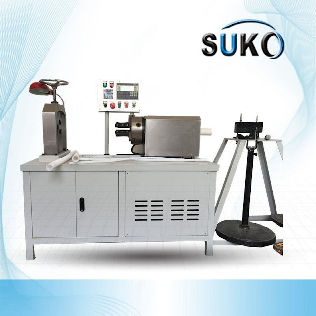
Corrugated Pipe Machine Features:
ü Power Consumption: 380V, 1.5KW.
ü Frequency Control, for the adjustment of OD: 10mm to 50mm.
ü Wall thickness: 1-2 mm PTFE convoluted hose.
ü Imported heating system is used.
ü heating temperature precision: + -1 degree.
ü Single person can operate two machines.
ü In case 16/18 PTFE convoluted hose hourly capacity of 15-35 meters.
Equipment Accessories Details:
ü A main engine.
ü host of supporting tail stock.
ü 10 special bracket of PTFE convoluted hose for the production.
ü 30 with the following specifications bellows mold set.
PTFE Convoluted Hose Features
ü To absorb effectively vibration, noise, thermal expansion from pipeline system.
ü To resolve minor deviation because of piping connecting and eliminate the pipeline residual stress.
ü Applied to repeated motion in high temperature areas, good anti-fatigue performance.
ü Good flexibility, resistant to high temperature, resistant to corrosion.
ü Applied in the fields of petroleum, chemical industry, aerospace, metallurgy, electricity, gas, building, mechanical, construction, iron and steel, paper making, fabric, medicine, food and vessels etc.
PTFE Convoluted Hose Characteristics
PTFE (Polytetrafluorethylene) has the lowest coefficient of friction of any material known to man. PTFE tubing features unmatched chemical resistance and a non-stick surface that facilitates flow and eliminates media buildup.
One key important advantage of PTFE convoluted hose is its operating temperature range, it can easily out perform other engineering plastics by being able to perform continuously at-250°C, right up to an amazing 250°C. Another important advantage of PTFE is its outstanding co-efficient of friction, PTFE convoluted hose is in the record books as having one of the lowest friction values known to man.
PTFE convoluted hose also has excellent acid and chemical resistance. Another feature of PTFE convoluted hose is its ability to set by or due to compression. PTFE convoluted hose has excellent electrical resistance. PTFE convoluted hose is also water repellent and is often used in the manufacture of modern high performing, water repellent and breath able clothing.
PTFE Convoluted Hose Applications
PTFE convoluted hose is excellent for low friction bearings, bushes, rollers and pulleys. PTFE convoluted hose is also almost exclusively used in cryogenic components due to its ultralow operating temperatures. PTFE convoluted hose is regularly used for seals. PTFE convoluted hose has become a very important engineering plastic used within the aerospace industry and aeronautics. PTFE convoluted hose is often used within the food industry companies. Another useful application over the years has been in the use of product or component handles due to its resistance to heat and heat transfer. When an application for electrical resistance becomes too high for other materials, PTFE convoluted hose can fill a very important gap.
ü Virgin Polytetrafluoroethylene resin ƒ
ü Chemically inert ƒ
ü Lowest coefficient of friction ƒ
ü Superior dielectric strength ƒ
ü Exceptional heat resistance ƒ
ü Self extinguishing ƒ
ü Non-wetting ƒ
ü Excellent flex life ƒ
ü Laser mark able
Applications/Markets
ü Cable Liner ƒ
ü Electrical Insulation ƒ
ü Oxygen Sensor ƒ
ü Paint Transfer ƒ
ü Gas Sampling ƒ
ü Laboratory
Corrugated Pipe Machine Features:
ü Power Consumption: 380V, 1.5KW.
ü Frequency Control, for the adjustment of OD: 10mm to 50mm.
ü Wall thickness: 1-2 mm PTFE convoluted hose.
ü Imported heating system is used.
ü heating temperature precision: + -1 degree.
ü Single person can operate two machines.
ü In case 16/18 PTFE convoluted hose hourly capacity of 15-35 meters.
Equipment Accessories Details:
ü A main engine.
ü host of supporting tail stock.
ü 10 special bracket of PTFE convoluted hose for the production.
ü 30 with the following specifications bellows mold set.
PTFE Convoluted Hose Features
ü To absorb effectively vibration, noise, thermal expansion from pipeline system.
ü To resolve minor deviation because of piping connecting and eliminate the pipeline residual stress.
ü Applied to repeated motion in high temperature areas, good anti-fatigue performance.
ü Good flexibility, resistant to high temperature, resistant to corrosion.
ü Applied in the fields of petroleum, chemical industry, aerospace, metallurgy, electricity, gas, building, mechanical, construction, iron and steel, paper making, fabric, medicine, food and vessels etc.
PTFE Convoluted Hose Characteristics
PTFE (Polytetrafluorethylene) has the lowest coefficient of friction of any material known to man. PTFE tubing features unmatched chemical resistance and a non-stick surface that facilitates flow and eliminates media buildup.
One key important advantage of PTFE convoluted hose is its operating temperature range, it can easily out perform other engineering plastics by being able to perform continuously at-250°C, right up to an amazing 250°C. Another important advantage of PTFE is its outstanding co-efficient of friction, PTFE convoluted hose is in the record books as having one of the lowest friction values known to man.
PTFE convoluted hose also has excellent acid and chemical resistance. Another feature of PTFE convoluted hose is its ability to set by or due to compression. PTFE convoluted hose has excellent electrical resistance. PTFE convoluted hose is also water repellent and is often used in the manufacture of modern high performing, water repellent and breath able clothing.
PTFE Convoluted Hose Applications
PTFE convoluted hose is excellent for low friction bearings, bushes, rollers and pulleys. PTFE convoluted hose is also almost exclusively used in cryogenic components due to its ultralow operating temperatures. PTFE convoluted hose is regularly used for seals. PTFE convoluted hose has become a very important engineering plastic used within the aerospace industry and aeronautics. PTFE convoluted hose is often used within the food industry companies. Another useful application over the years has been in the use of product or component handles due to its resistance to heat and heat transfer. When an application for electrical resistance becomes too high for other materials, PTFE convoluted hose can fill a very important gap.
ü Virgin Polytetrafluoroethylene resin ƒ
ü Chemically inert ƒ
|
Метки: Corrugated Pipe Corrugated Pipe Machine Machine Plastic PTFE PTFE Corrugated Pipe Machine |
Polymer micro - mechanical mold assembly molding |
In-mold assembly molding of polymer micromachines is a new technology in which technological bottlenecks of micromachines micro-assembly manufacturing process can be effectively solved, however, the thermal-fluid-solid coupling effect between polymer high temperature viscoelastic melt flow and preformed micro solid part can be caused which induces preformed micro solid part producing frequently the thermal-fluid-solid coupling deformation and necking fusing fracture phenomenon, how accurate control and predict thermal-fluid-solid coupling deformation and necking fusing fracture phenomenon is key scientific issues of in mold micro assembly molding technology industrialized application.
Therefore, based on the developed variable combination mold and Auto model FB-110C polymer co-injection molding machine, the polymer micromachines In-mold assembly molding experimental research platform was established, by which the influencing rule and influencing mechanism of process parameters and properties of polymeric materials on preformed micro shaft thermal-fluid-solid coupling deformation and necking fusing fracture phenomenon were systematically studied, key regulatory parameters of thermal-fluid-solid coupling deformation and necking fusing fracture phenomenon in in-mold micro assembly molding process was clarified; the scientific foundation of the research and development of thermal-fluid-solid coupling deformation precision-shaped control technology and the prevention technology of necking fusing fracture phenomenon was laid. The main innovations and achievements as follows.
The variable combination mold of typical micro mobile motion pair in-mold micro assembly molding was developed, and Based on the developed variable combination mold and Auto model FB-110C polymer co-injection molding machine, the polymer micromachines In-mold assembly molding experimental research platform was established.
The influencing rule and influencing mechanism of secondary molding melt injection temperature, secondary molding melt injection pressure and screw stroke on necking fusing fracture phenomenon of preformed micro shaft, the research results show key regulatory parameter of preformed micro shaft necking fusing fracture phenomenon is secondary molding melt injection volume, when the secondary molding melt injection volume exceeds its critical melt injection volume, the critical melt injection volume of induced preformed micro shaft necking fusing fracture phenomenon depends on secondary molding melt injection temperature, which is positively proportional to secondary molding melt injection temperature. Improving of secondary molding melt injection temperature will help improve the critical melt injection volume of induced preformed micro shaft necking fusing fracture phenomenon, which increase the secondary molded part density and strength in In-mold assembly molding process, at the same time, but also to avoid preformed micro shaft necking fusing fracture phenomenon.
Experimental research results show that the micro shaft unidirectional necking fusing fracture phenomenon possible ways have two main factors, firstly, the axial tensile force is too large; secondly, the preformed micro shaft near-surface temperature in a secondary molding process is too large, which led to partial melting and a sharp decline of elastic modulus. The heat transforms time contact between secondary molding high temperature and preformed micro shaft will prolong with increasing of secondary molding melt injection volume, which make the preformed micro shaft near-surface temperature improve with increasing of screw stroke.
When the preform micro shaft near-surface temperature exceeds the glass transition temperature, local micro assembly interface of preformed micro shaft will experience continuous phase transition evolution from elastoplastic solid state to viscoelastic plasticity glassy state ,final to viscoelastic high-elastic state, which led to a sharp decline of elastic modulus and make polymer material in local phase transition evolution region lost the ability to resist deformation, preformed micro shaft in local phase transition evolution region of micro assembly interface must produce necking phenomenon under tensile force effect.
When the tension force reaches a certain level, preformed micro shaft will produce the necking fusing fracture phenomenon. In order to preform micro shaft near-surface temperature does not exceed the glass transition temperature, which requires its secondary molding melt injection volume does not exceed the critical injection volume. Based on above necking fusing fracture mechanism, the preparatory proposed necking fusing fracture mechanism theory and prevention technical method of preformed micro shaft necking fusing fracture provide technical support for the industrialized application of In-mold micro assembly molding technology.
Experimental research results show that the preformed micro shaft thermal-fluid-solid coupling deformation depends on secondary molding melt injection temperature,secondary molding melt injection pressure ,secondary molding melt injection volume and preformed micro shaft material properties,and the process parameters affect its thermal-fluid-solid coupling deformation by adjusting pre-formed micro shaft micro assembly interface to withstand the impact of the thermal-fluid-solid coupling pressure, viscoelastic supporting normal stress, viscous friction drag shear stress and micro shaft stiffness against deformation,the preformed micro shaft thermal-fluid-solid coupling deformation increase with increasing of secondary molding melt injection temperature,secondary molding melt injection pressure, secondary molding melt injection volume, and based on key regulatory parameters of viscoelastic supporting normal stress, viscous friction drag shear stress and micro shaft stiffness against deformation, the formation mechanism of preformed micro shaft thermal-fluid-solid coupling deformation was revealed.
[---This article is from the network, if there is infringement, please contact delete, thank you!--- ]

In-mold assembly molding of polymer micromachines is a new technology in which technological bottlenecks of micromachines micro-assembly manufacturing process can be effectively solved, however, the thermal-fluid-solid coupling effect between polymer high temperature viscoelastic melt flow and preformed micro solid part can be caused which induces preformed micro solid part producing frequently the thermal-fluid-solid coupling deformation and necking fusing fracture phenomenon, how accurate control and predict thermal-fluid-solid coupling deformation and necking fusing fracture phenomenon is key scientific issues of in mold micro assembly molding technology industrialized application.
Therefore, based on the developed variable combination mold and Auto model FB-110C polymer co-injection molding machine, the polymer micromachines In-mold assembly molding experimental research platform was established, by which the influencing rule and influencing mechanism of process parameters and properties of polymeric materials on preformed micro shaft thermal-fluid-solid coupling deformation and necking fusing fracture phenomenon were systematically studied, key regulatory parameters of thermal-fluid-solid coupling deformation and necking fusing fracture phenomenon in in-mold micro assembly molding process was clarified; the scientific foundation of the research and development of thermal-fluid-solid coupling deformation precision-shaped control technology and the prevention technology of necking fusing fracture phenomenon was laid. The main innovations and achievements as follows.
The variable combination mold of typical micro mobile motion pair in-mold micro assembly molding was developed, and Based on the developed variable combination mold and Auto model FB-110C polymer co-injection molding machine, the polymer micromachines In-mold assembly molding experimental research platform was established.
The influencing rule and influencing mechanism of secondary molding melt injection temperature, secondary molding melt injection pressure and screw stroke on necking fusing fracture phenomenon of preformed micro shaft, the research results show key regulatory parameter of preformed micro shaft necking fusing fracture phenomenon is secondary molding melt injection volume, when the secondary molding melt injection volume exceeds its critical melt injection volume, the critical melt injection volume of induced preformed micro shaft necking fusing fracture phenomenon depends on secondary molding melt injection temperature, which is positively proportional to secondary molding melt injection temperature. Improving of secondary molding melt injection temperature will help improve the critical melt injection volume of induced preformed micro shaft necking fusing fracture phenomenon, which increase the secondary molded part density and strength in In-mold assembly molding process, at the same time, but also to avoid preformed micro shaft necking fusing fracture phenomenon.
Experimental research results show that the micro shaft unidirectional necking fusing fracture phenomenon possible ways have two main factors, firstly, the axial tensile force is too large; secondly, the preformed micro shaft near-surface temperature in a secondary molding process is too large, which led to partial melting and a sharp decline of elastic modulus. The heat transforms time contact between secondary molding high temperature and preformed micro shaft will prolong with increasing of secondary molding melt injection volume, which make the preformed micro shaft near-surface temperature improve with increasing of screw stroke.
When the preform micro shaft near-surface temperature exceeds the glass transition temperature, local micro assembly interface of preformed micro shaft will experience continuous phase transition evolution from elastoplastic solid state to viscoelastic plasticity glassy state ,final to viscoelastic high-elastic state, which led to a sharp decline of elastic modulus and make polymer material in local phase transition evolution region lost the ability to resist deformation, preformed micro shaft in local phase transition evolution region of micro assembly interface must produce necking phenomenon under tensile force effect.
When the tension force reaches a certain level, preformed micro shaft will produce the necking fusing fracture phenomenon. In order to preform micro shaft near-surface temperature does not exceed the glass transition temperature, which requires its secondary molding melt injection volume does not exceed the critical injection volume. Based on above necking fusing fracture mechanism, the preparatory proposed necking fusing fracture mechanism theory and prevention technical method of preformed micro shaft necking fusing fracture provide technical support for the industrialized application of In-mold micro assembly molding technology.
Experimental research results show that the preformed micro shaft thermal-fluid-solid coupling deformation depends on secondary molding melt injection temperature,secondary molding melt injection pressure ,secondary molding melt injection volume and preformed micro shaft material properties,and the process parameters affect its thermal-fluid-solid coupling deformation by adjusting pre-formed micro shaft micro assembly interface to withstand the impact of the thermal-fluid-solid coupling pressure, viscoelastic supporting normal stress, viscous friction drag shear stress and micro shaft stiffness against deformation,the preformed micro shaft thermal-fluid-solid coupling deformation increase with increasing of secondary molding melt injection temperature,secondary molding melt injection pressure, secondary molding melt injection volume, and based on key regulatory parameters of viscoelastic supporting normal stress, viscous friction drag shear stress and micro shaft stiffness against deformation, the formation mechanism of preformed micro shaft thermal-fluid-solid coupling deformation was revealed.
[---This article is from the network, if there is infringement, please contact delete, thank you!--- ]
|
Метки: in-mold assembly molding polymer material Polymer polymer molding molding |
Measurement for shear viscosity spectrum of polymer melts by using screw extruder capillary |
Most polymer materials are processed in the melt state, which involves melt flow and deformation, which not only affects the processing process itself, but also affects the final performance of the product. Therefore, the study of rheological properties of polymer materials has been a hot topic. Accurate measurement of rheological parameters is the basis of in-depth study of rheological properties.
Shear viscosity is an important parameter to characterize the rheological behavior. The so-called shear viscosity of polymer melt is the ratio of shear stress and shear rate that melt is subjected to in the process of flow. Polymer melt causes pseudoplastic fluid, and its flow behavior has the characteristics of shear thinning. It is usually necessary to use the relationship curve between shear viscosity and shear rate, namely shear viscosity spectrum, to fully reflect the processing characteristics of polymer melt.
The basic method of measuring melt viscosity is to try to make the melt flow through a long and thin capillary tube, such as a round capillary tube. The shear stress can be calculated by measuring the pressure drop at both ends of the melt as it flows through the capillary tube. The shear rate can be calculated by measuring the flux of melt per unit time. Thus the melt viscosity can be obtained.
The conventional way to get the melt out of the capillary tube is to use piston propulsion. The advantage of this method is that it USES fewer test materials and can obtain higher shear stress. The high pressure capillary rheometer is based on this principle [4].However, the disadvantage of this test method is that the material cannot be tested under the actual processing conditions, and it is difficult to obtain the rheological properties of the polymer melt when it is processed. Especially in the study of blending modification of several polymer materials, the polymer melt needs the strong shearing action of screw to achieve the purpose of blending. High pressure capillary rheometer is not suitable for testing such materials.
The screw extrusion capillary rheological test device can solve the above problems. The device USES the propulsive force of the screw to make the polymer melt flow through the capillary tube. Therefore, the shear viscosity of polymer melt can be measured under conditions closer to real processing. This method is particularly suitable for the measurement of the rheological properties of thermoplastic materials and their mixtures. Because the measurement simulates the real experimental environment, the obtained test parameters can more accurately describe the behavior of materials in actual processing.
Shear viscosity spectra of polymer melts can be measured using specialized test instruments, such as high pressure capillary rheometers, or combined revolutions. However, these devices are expensive and limited in practical use, especially in the application of large-scale industrial production. In fact, it is not necessary to rely on the special test instrument, as long as the shear viscosity test principle, you can use a simple small single-screw extruder and capillary mold, constitute a low-cost shear viscosity spectrum test device. Combined with computer data processing, the shear viscosity spectrum of polymer melt can be easily and quickly obtained. This method is especially suitable for small and medium-sized enterprises to carry out product development and raw material inspection.

Most polymer materials are processed in the melt state, which involves melt flow and deformation, which not only affects the processing process itself, but also affects the final performance of the product. Therefore, the study of rheological properties of polymer materials has been a hot topic. Accurate measurement of rheological parameters is the basis of in-depth study of rheological properties.
Shear viscosity is an important parameter to characterize the rheological behavior. The so-called shear viscosity of polymer melt is the ratio of shear stress and shear rate that melt is subjected to in the process of flow. Polymer melt causes pseudoplastic fluid, and its flow behavior has the characteristics of shear thinning. It is usually necessary to use the relationship curve between shear viscosity and shear rate, namely shear viscosity spectrum, to fully reflect the processing characteristics of polymer melt.
The basic method of measuring melt viscosity is to try to make the melt flow through a long and thin capillary tube, such as a round capillary tube. The shear stress can be calculated by measuring the pressure drop at both ends of the melt as it flows through the capillary tube. The shear rate can be calculated by measuring the flux of melt per unit time. Thus the melt viscosity can be obtained.
The conventional way to get the melt out of the capillary tube is to use piston propulsion. The advantage of this method is that it USES fewer test materials and can obtain higher shear stress. The high pressure capillary rheometer is based on this principle [4].However, the disadvantage of this test method is that the material cannot be tested under the actual processing conditions, and it is difficult to obtain the rheological properties of the polymer melt when it is processed. Especially in the study of blending modification of several polymer materials, the polymer melt needs the strong shearing action of screw to achieve the purpose of blending. High pressure capillary rheometer is not suitable for testing such materials.
The screw extrusion capillary rheological test device can solve the above problems. The device USES the propulsive force of the screw to make the polymer melt flow through the capillary tube. Therefore, the shear viscosity of polymer melt can be measured under conditions closer to real processing. This method is particularly suitable for the measurement of the rheological properties of thermoplastic materials and their mixtures. Because the measurement simulates the real experimental environment, the obtained test parameters can more accurately describe the behavior of materials in actual processing.
Shear viscosity spectra of polymer melts can be measured using specialized test instruments, such as high pressure capillary rheometers, or combined revolutions. However, these devices are expensive and limited in practical use, especially in the application of large-scale industrial production. In fact, it is not necessary to rely on the special test instrument, as long as the shear viscosity test principle, you can use a simple small single-screw extruder and capillary mold, constitute a low-cost shear viscosity spectrum test device. Combined with computer data processing, the shear viscosity spectrum of polymer melt can be easily and quickly obtained. This method is especially suitable for small and medium-sized enterprises to carry out product development and raw material inspection.
|
Метки: polymer tube extruder screw extruder extrusion Polymer melt polymer materials plastic shear viscosity |
Polymer plasticized compounding extruder screw design |
Screw is the most important part of extruder, can be said to be the heart of the extruder, it can directly affect the application of the extruder and production efficiency. The performance of screw determines the productivity, plasticizing quality, dispersion of filler, melt temperature and power consumption of an extruder. Through the screw rotation, the polymer plastic can be extruded, and the plastic can move, pressurize and obtain some heat from friction in the cylinder. During the movement of the cylinder, the plastic can be mixed and plasticized.
1. The screw structure of polymer plasticizing and mixing extruder.
During processing, when the material moves forward along the screw, it experiences changes in temperature, pressure, viscosity, etc., which are different within the full length range of the screw. There are three physical states of polymer plastic in extruder: glass state, high elastic state and viscous flow state. In order to adapt to the requirements of different states and according to the changing characteristics of the material, the screw can be divided into three sections: feed section, compress section and homogenize section.
The function of the feeding section is to feed the material supplied by the hopper to the compression section. During the movement of the plastic, it generally remains a solid state and partially melts due to heat. The length of the feeding section varies with the type of plastic. Compression section (transfer section) is the role of physical material pressure, so that the material from solid into molten, well out of the air in the material; In order to adapt to the characteristics of reducing the volume when pushing the gas in the material back to the feeding section, pressing the material and melting the material, the screw in this section should produce greater shearing effect and compression of the plastic.
The function of the homogenizing section (metering section) is to feed the molten material to the machine head at constant volume (volume) and pressure so that it is formed in the mouth mold. The volume of the spiral groove in the homogenizing section is the same as that in the feeding section.
In order to avoid material retention in the end of the screw head dead corner, causing decomposition, screw head is often designed into a cone or semicircle; Some screw homogenization section is - the surface is completely smooth body called torpedo head, but there are also engraved grooves or milling patterns. The torpedo head has the function of stirring and controlling the material, eliminating pulsating (pulsating) phenomenon in the flow, reducing the thickness of the material layer with increasing the pressure of the material, improving the heating condition, and further improving the screw plasticizing efficiency.
According to melt transport theory, melt flows in the screw homogenization section in four forms, and the flow of molten material in the screw groove is a combination of these four flows: positive flow -- plastic melt flows between the cylinder and the screw in the direction of the screw groove toward the machine head. Counter-current flow direction is opposite to the positive flow, which is caused by the pressure gradient caused by the resistance of the nose, porous plate and filter plate. The flow of the melt in a direction perpendicular to the thread wall affects the mixing and heat exchange of the melt during extrusion. Leakage flow - a backflow formed by the pressure gradient between the screw and the cylinder, along the axial direction of the screw. Different flow patterns have important effects on the mixing uniformity of polymers.
Screw diameter and the determination of structural form, mainly according to the production of product output, specifications, types of processed materials and various structural screw characteristics to determine. Generally, the feeding section of the screw has a deeper groove and the groove depth is unchanged, compression section (melt section) of the screw groove depth along the direction of discharge from the deep to shallow, metering section (homogenized section) of the screw has a shallow groove and the groove depth is unchanged.
2. The screw material.
Screw is the key part of extruder, as the material of screw must have high temperature resistance, wear resistance, corrosion resistance, high strength and other characteristics, at the same time should have good cutting performance, heat treatment residual stress, small thermal deformation and other characteristics. For extruder screw material, there are specific requirements as follows:
(1) High mechanical properties. To have enough strength, to adapt to high temperature, high pressure working conditions, improve the service life of the screw.
(2) Good machining performance. Good machining performance and heat treatment performance.
(3) Good corrosion and wear resistance.
(4) Easy to draw.

Screw is the most important part of extruder, can be said to be the heart of the extruder, it can directly affect the application of the extruder and production efficiency. The performance of screw determines the productivity, plasticizing quality, dispersion of filler, melt temperature and power consumption of an extruder. Through the screw rotation, the polymer plastic can be extruded, and the plastic can move, pressurize and obtain some heat from friction in the cylinder. During the movement of the cylinder, the plastic can be mixed and plasticized.
1. The screw structure of polymer plasticizing and mixing extruder.
During processing, when the material moves forward along the screw, it experiences changes in temperature, pressure, viscosity, etc., which are different within the full length range of the screw. There are three physical states of polymer plastic in extruder: glass state, high elastic state and viscous flow state. In order to adapt to the requirements of different states and according to the changing characteristics of the material, the screw can be divided into three sections: feed section, compress section and homogenize section.
The function of the feeding section is to feed the material supplied by the hopper to the compression section. During the movement of the plastic, it generally remains a solid state and partially melts due to heat. The length of the feeding section varies with the type of plastic. Compression section (transfer section) is the role of physical material pressure, so that the material from solid into molten, well out of the air in the material; In order to adapt to the characteristics of reducing the volume when pushing the gas in the material back to the feeding section, pressing the material and melting the material, the screw in this section should produce greater shearing effect and compression of the plastic.
The function of the homogenizing section (metering section) is to feed the molten material to the machine head at constant volume (volume) and pressure so that it is formed in the mouth mold. The volume of the spiral groove in the homogenizing section is the same as that in the feeding section.
In order to avoid material retention in the end of the screw head dead corner, causing decomposition, screw head is often designed into a cone or semicircle; Some screw homogenization section is - the surface is completely smooth body called torpedo head, but there are also engraved grooves or milling patterns. The torpedo head has the function of stirring and controlling the material, eliminating pulsating (pulsating) phenomenon in the flow, reducing the thickness of the material layer with increasing the pressure of the material, improving the heating condition, and further improving the screw plasticizing efficiency.
According to melt transport theory, melt flows in the screw homogenization section in four forms, and the flow of molten material in the screw groove is a combination of these four flows: positive flow -- plastic melt flows between the cylinder and the screw in the direction of the screw groove toward the machine head. Counter-current flow direction is opposite to the positive flow, which is caused by the pressure gradient caused by the resistance of the nose, porous plate and filter plate. The flow of the melt in a direction perpendicular to the thread wall affects the mixing and heat exchange of the melt during extrusion. Leakage flow - a backflow formed by the pressure gradient between the screw and the cylinder, along the axial direction of the screw. Different flow patterns have important effects on the mixing uniformity of polymers.
Screw diameter and the determination of structural form, mainly according to the production of product output, specifications, types of processed materials and various structural screw characteristics to determine. Generally, the feeding section of the screw has a deeper groove and the groove depth is unchanged, compression section (melt section) of the screw groove depth along the direction of discharge from the deep to shallow, metering section (homogenized section) of the screw has a shallow groove and the groove depth is unchanged.
2. The screw material.
Screw is the key part of extruder, as the material of screw must have high temperature resistance, wear resistance, corrosion resistance, high strength and other characteristics, at the same time should have good cutting performance, heat treatment residual stress, small thermal deformation and other characteristics. For extruder screw material, there are specific requirements as follows:
(1) High mechanical properties. To have enough strength, to adapt to high temperature, high pressure working conditions, improve the service life of the screw.
(2) Good machining performance. Good machining performance and heat treatment performance.
(3) Good corrosion and wear resistance.
(4) Easy to draw.
|
Метки: polymer plastic plasticizing extruder extrusion polymer plastic polymer extruder machine |
Teflon coating is introduced |
1. Antifouling finishing properties of (PTFE)teflon coatings
(1)The clothes
Keeping their clothes clean is no longer a problem for many children returning to school after the holidays. Their tracksuits, skirts and trousers are treated with teflon-coated anti-fouling, which keeps the children's clothes looking sleek and tidy. The clothes also stand the toughest tests of comfort, even when they are close to sensitive parts of the body. For office workers, leaving coffee stains or ink stains on their clothes can be embarrassing. Make consumers' life more comfortable.
(2)Leather aspect
(PTFE)Teflon coated antifouling finish gives leather perfect waterproof and antifouling protection. But when it comes to vision, taste and touch, consumers are unaware of the TeflonB coating.
(3)other aspects
Teflon coating finishing is not only used in the field of clothing and leather, but also widely used in luggage, umbrella and other textile products, hunting and fishing and other recreational textiles, bedding, all kinds of decorative textiles and so on.
Surface properties:
The molecules slide easily between each other, and the friction coefficient is the lowest in all polymers. It has good lubricity, is difficult to be wetted by ordinary liquid, and has little adhesion to other substances.
Chemical resistance:
Teflon is even more resistant to chemical corrosion than rare metals. Except perfluoroalkane and perchloroalkane can make it slightly swelling, ketones, ethers and other organic solvents can not act on it. Because (PTFE)teflon has little wettability, its absorption rate to acid and alkali solvent is very low. Even at high temperature, concentrated acid, concentrated alkali and strong oxidant cannot react with teflon uplift.
Heat and climate resistance:
Teflon has good thermal stability, and is not affected by oxygen, ozone and ultraviolet radiation, and is not easy to age. The combustion oxygen index of teflon is greater than 95, which is incombustible.

1. Antifouling finishing properties of (PTFE)teflon coatings
(1)The clothes
Keeping their clothes clean is no longer a problem for many children returning to school after the holidays. Their tracksuits, skirts and trousers are treated with teflon-coated anti-fouling, which keeps the children's clothes looking sleek and tidy. The clothes also stand the toughest tests of comfort, even when they are close to sensitive parts of the body. For office workers, leaving coffee stains or ink stains on their clothes can be embarrassing. Make consumers' life more comfortable.
(2)Leather aspect
(PTFE)Teflon coated antifouling finish gives leather perfect waterproof and antifouling protection. But when it comes to vision, taste and touch, consumers are unaware of the TeflonB coating.
(3)other aspects
Teflon coating finishing is not only used in the field of clothing and leather, but also widely used in luggage, umbrella and other textile products, hunting and fishing and other recreational textiles, bedding, all kinds of decorative textiles and so on.
Surface properties:
The molecules slide easily between each other, and the friction coefficient is the lowest in all polymers. It has good lubricity, is difficult to be wetted by ordinary liquid, and has little adhesion to other substances.
Chemical resistance:
Teflon is even more resistant to chemical corrosion than rare metals. Except perfluoroalkane and perchloroalkane can make it slightly swelling, ketones, ethers and other organic solvents can not act on it. Because (PTFE)teflon has little wettability, its absorption rate to acid and alkali solvent is very low. Even at high temperature, concentrated acid, concentrated alkali and strong oxidant cannot react with teflon uplift.
Heat and climate resistance:
Teflon has good thermal stability, and is not affected by oxygen, ozone and ultraviolet radiation, and is not easy to age. The combustion oxygen index of teflon is greater than 95, which is incombustible.
|
Метки: PTFE teflon coating teflon coatings Teflon coated PTFE coating products |
Innovation of industrial furnace combustion technology |
Industrial furnaces are mainly divided into smelting casting and heat treatment furnace two types. The former is used for refining and smelting casting, while the latter is used for heating and heat treatment of billets before processing. Most of the fuel used for metal heating is natural gas or city gas, which must be fed into the air by air blower to support combustion.
As we all know, the air is composed of nitrogen, which accounts for 78%, and oxygen, which accounts for 21% (and about 1% of the noble gases). Nitrogen, which has no combustion effect, becomes a drag, which not only delays the heating speed, but also takes away the heat in the flue gas, adding to the environmental problems. After years of research and development, The Linde Group of Germany has invented The low-temperature pure oxygen combustion technology (LTOF), which is suitable for smelting, melting casting and heat treatment of non-ferrous metals such as steel, copper and aluminum.
1. Introduction of low temperature pure oxygen combustion technology (LTOF) in industrial furnace
The main effects of pure oxygen combustion technology are:
(1) No nitrogen enters the furnace;
(2) No nitrogen removes heat in the flue gas;
(3) Iincrease the efficiency of radiation heat transfer;
(4) The flue gas stays longer in the furnace, so as to improve the heat transfer effect;
(5) Since there is no nitrogen in combustion supporting gas, it has little impact on environmental protection when discharged;
(6) The combustion supporting effect of pure oxygen reaches 77%, while the atmospheric combustion supporting rate is only 23%.
2. Advantages of low temperature pure oxygen burner (LTOF) flame in industrial furnace
The objective of low temperature pure oxygen combustion (LTOF) technology development is to improve the melting capacity and efficiency of reflector. The unique LTOF burner allows the flue gas from the entrainment furnace to enter the burner mixing zone, diluting the oxygen concentration at the front of the burner and slowing down the rate of combustion reaction, resulting in a lower flame temperature that is close to the flame of air-fuel combustion.
This LTOF pure oxygen combustion flame characteristics make the temperature in the furnace more uniform, eliminate local hot spots, reduce fuel consumption, reduce flue gas emissions and improve metal recovery rate. Comparison between air combustion and low-temperature pure oxygen combustion, among which, air combustion, burner power is 311kW, water cooling is 231kW, the average constantly measured in molten aluminum is 1131℃, and heat flux is 79kW/m2.Low-temperature pure oxygen combustion, burner power 257kW, water cooling 66kW, continuous measurement of aluminum in the average value of 1152℃, heat flux 79kW/m2.
3. Flame form of LTOF low-temperature pure oxygen burner in industrial furnace, flame free combustion is the most effective
(1) Can reduce NOx emission by 90%;
(2) Compared with regenerative or ordinary pure oxygen combustion, flameless combustion is the least sensitive to air leakage, and there is no significant change in NOx production. The average energy consumption and thermal balance of LTOF pure oxygen combustion technology in 28t aluminum alloy melting reflector.

Industrial furnaces are mainly divided into smelting casting and heat treatment furnace two types. The former is used for refining and smelting casting, while the latter is used for heating and heat treatment of billets before processing. Most of the fuel used for metal heating is natural gas or city gas, which must be fed into the air by air blower to support combustion.
As we all know, the air is composed of nitrogen, which accounts for 78%, and oxygen, which accounts for 21% (and about 1% of the noble gases). Nitrogen, which has no combustion effect, becomes a drag, which not only delays the heating speed, but also takes away the heat in the flue gas, adding to the environmental problems. After years of research and development, The Linde Group of Germany has invented The low-temperature pure oxygen combustion technology (LTOF), which is suitable for smelting, melting casting and heat treatment of non-ferrous metals such as steel, copper and aluminum.
1. Introduction of low temperature pure oxygen combustion technology (LTOF) in industrial furnace
The main effects of pure oxygen combustion technology are:
(1) No nitrogen enters the furnace;
(2) No nitrogen removes heat in the flue gas;
(3) Iincrease the efficiency of radiation heat transfer;
(4) The flue gas stays longer in the furnace, so as to improve the heat transfer effect;
(5) Since there is no nitrogen in combustion supporting gas, it has little impact on environmental protection when discharged;
(6) The combustion supporting effect of pure oxygen reaches 77%, while the atmospheric combustion supporting rate is only 23%.
2. Advantages of low temperature pure oxygen burner (LTOF) flame in industrial furnace
The objective of low temperature pure oxygen combustion (LTOF) technology development is to improve the melting capacity and efficiency of reflector. The unique LTOF burner allows the flue gas from the entrainment furnace to enter the burner mixing zone, diluting the oxygen concentration at the front of the burner and slowing down the rate of combustion reaction, resulting in a lower flame temperature that is close to the flame of air-fuel combustion.
This LTOF pure oxygen combustion flame characteristics make the temperature in the furnace more uniform, eliminate local hot spots, reduce fuel consumption, reduce flue gas emissions and improve metal recovery rate. Comparison between air combustion and low-temperature pure oxygen combustion, among which, air combustion, burner power is 311kW, water cooling is 231kW, the average constantly measured in molten aluminum is 1131℃, and heat flux is 79kW/m2.Low-temperature pure oxygen combustion, burner power 257kW, water cooling 66kW, continuous measurement of aluminum in the average value of 1152℃, heat flux 79kW/m2.
3. Flame form of LTOF low-temperature pure oxygen burner in industrial furnace, flame free combustion is the most effective
(1) Can reduce NOx emission by 90%;
(2) Compared with regenerative or ordinary pure oxygen combustion, flameless combustion is the least sensitive to air leakage, and there is no significant change in NOx production. The average energy consumption and thermal balance of LTOF pure oxygen combustion technology in 28t aluminum alloy melting reflector.
|
Метки: furnace industrial furnace environmental protection low temperature pure oxygen fuel polymer furnace |
Design of microwave sintering furnace |
1. Principle of microwave sintering of ceramic materials
The reaction of materials to microwave can be divided into four situations: microwave reflection microwave transmission; microwave absorption; partial absorption of microwave. Most metals fall into the first category, while all glass and ceramic materials fall into the latter three categories. When a ceramic body is placed in a microwave field, the absorbed power can be expressed by the following equation:
P = (2π fε ) ( E2/ 2) tan δ,When the microwave penetrates the material, its intensity decreases with the penetration depth. The distance from the material surface to the attenuation to 1/ e of microwave energy is defined as the penetration depth Dp of microwave:
3λ 0
DP = π tan δ (ε r/ε 0) 1/ 2
8. 686
Where, P is the microwave power absorbed by the ceramic body; F is the frequency; ε is the composite dielectric constant; λ 0 is the wavelength of microwave in vacuum; E is the intensity of electric field; tan δ is the loss tangent of dielectric ceramics; The loss tangent (the ratio of the loss factor to the dielectric constant) is usually used to express the coupling capability of the material to the microwave.The higher the loss tangent value is, the stronger the coupling ability between the material and microwave is.
2. Design of microwave high temperature heating furnace
Microwave heating furnace is mainly composed of monitoring system, control system, insulation box, microwave generator, heating box and gas storage tank. The heating box is made of stainless steel mirror plate. Cooling water can flow in the sandwich between two layers of stainless steel plate to achieve the cooling of heating box. The temperature sensor we use is RAYR3I1MSCL2U infrared thermometer of American leitai company. The control system can realize manual control and automatic control. In order to prevent in the microwave oven door closed after microwave heating furnace from the oven door and leak out of the gaps between the cavity, in addition to heating furnace door in processing and manufacturing to ensure the high dimensional precision and assembly precision, we in the microwave oven door installed around the choke groove structure, this structure can effectively reduce the leakage of microwave. The selection, field design and insulation of the microwave generator are the key factors in the sintering furnace design.
3. Microwave generator selection
Mag netron, Klystron and Gyrotron are generally selected in microwave heating devices. As the "heart" of microwave sintering equipment, its choice will directly affect the performance and cost of the whole equipment. The commonly used frequency in microwave sintering device is:
915 MHz, 2.45 GHz, 6 GHz, 28 GHz and 60 GHz, etc. Generally, magnetron can be selected as microwave generator for lower frequencies such as 915 MHz and 2.45 GHz,6 GHz can be selected as speed regulating tube, and higher frequencies such as 28 GHz and 60 GHz can be selected as magnetic coil.
As the frequency and power of various microwave generators increase, their price ratio ($/ Watt) will increase significantly. If high power microwave generator is needed in the design, it is recommended to use the same frequency and low power generator to obtain by power superposition.
4.Design of insulation structure
The most commonly used insulation structure in microwave sintering furnace is buried powder type and box type. Buried powder insulation structure has the advantages of good insulation effect. However, when samples are sintered at a higher temperature, adhesion between samples and buried powder is easy to occur. After the samples are sintered, direct contact will occur. But this structure is not as good as buried powder insulation structure. Combining the characteristics of two insulation structures, we designed a box-type insulation structure.

1. Principle of microwave sintering of ceramic materials
The reaction of materials to microwave can be divided into four situations: microwave reflection microwave transmission; microwave absorption; partial absorption of microwave. Most metals fall into the first category, while all glass and ceramic materials fall into the latter three categories. When a ceramic body is placed in a microwave field, the absorbed power can be expressed by the following equation:
P = (2π fε ) ( E2/ 2) tan δ,When the microwave penetrates the material, its intensity decreases with the penetration depth. The distance from the material surface to the attenuation to 1/ e of microwave energy is defined as the penetration depth Dp of microwave:
3λ 0
DP = π tan δ (ε r/ε 0) 1/ 2
8. 686
Where, P is the microwave power absorbed by the ceramic body; F is the frequency; ε is the composite dielectric constant; λ 0 is the wavelength of microwave in vacuum; E is the intensity of electric field; tan δ is the loss tangent of dielectric ceramics; The loss tangent (the ratio of the loss factor to the dielectric constant) is usually used to express the coupling capability of the material to the microwave.The higher the loss tangent value is, the stronger the coupling ability between the material and microwave is.
2. Design of microwave high temperature heating furnace
Microwave heating furnace is mainly composed of monitoring system, control system, insulation box, microwave generator, heating box and gas storage tank. The heating box is made of stainless steel mirror plate. Cooling water can flow in the sandwich between two layers of stainless steel plate to achieve the cooling of heating box. The temperature sensor we use is RAYR3I1MSCL2U infrared thermometer of American leitai company. The control system can realize manual control and automatic control. In order to prevent in the microwave oven door closed after microwave heating furnace from the oven door and leak out of the gaps between the cavity, in addition to heating furnace door in processing and manufacturing to ensure the high dimensional precision and assembly precision, we in the microwave oven door installed around the choke groove structure, this structure can effectively reduce the leakage of microwave. The selection, field design and insulation of the microwave generator are the key factors in the sintering furnace design.
3. Microwave generator selection
Mag netron, Klystron and Gyrotron are generally selected in microwave heating devices. As the "heart" of microwave sintering equipment, its choice will directly affect the performance and cost of the whole equipment. The commonly used frequency in microwave sintering device is:
915 MHz, 2.45 GHz, 6 GHz, 28 GHz and 60 GHz, etc. Generally, magnetron can be selected as microwave generator for lower frequencies such as 915 MHz and 2.45 GHz,6 GHz can be selected as speed regulating tube, and higher frequencies such as 28 GHz and 60 GHz can be selected as magnetic coil.
As the frequency and power of various microwave generators increase, their price ratio ($/ Watt) will increase significantly. If high power microwave generator is needed in the design, it is recommended to use the same frequency and low power generator to obtain by power superposition.
4.Design of insulation structure
The most commonly used insulation structure in microwave sintering furnace is buried powder type and box type. Buried powder insulation structure has the advantages of good insulation effect. However, when samples are sintered at a higher temperature, adhesion between samples and buried powder is easy to occur. After the samples are sintered, direct contact will occur. But this structure is not as good as buried powder insulation structure. Combining the characteristics of two insulation structures, we designed a box-type insulation structure.
|
Метки: microwave sintering furnace microwave sintering Automatic ceramic materials |
Polymer plastic properties |
1.Definition
The main components of polymer plastics are mainly polymer compounds, whose molecular weight is about 1 000, which is only for the physical concept. At present, polymer plastics are widely used, but the daily use of plastic is synthesized by polymer compounds, usually called high or macromolecule, is synthesized by monomer raw materials or raw materials into integrated materials, and through the later development, and fusion resin, color, stabilizer and other additives. The shape of polymer plastic can be changed freely and can be designed according to the user's requirements.
2.Characteristics
Polymer plastics not only have their own unique, that is, arbitrary changes in the shape, but also have viscoelasticity. Polymer plastic, if subjected to external forces, its body will produce high elastic deformation, viscous flow, polymer plastic deformation is mainly related to time. In addition, polymer plastic also has high specific strength, low strength and other characteristics, the strength of polymer plastic is generally lower, but its density is lower, so the strength becomes higher. Polymer has many characteristics, such as high stability, high wear resistance, expansion, high insulation, so it is widely used in various fields, by many people's favor.
The types of polymer plastics are also diverse. At present, the classification of polymer plastics in China mainly includes seven categories: rubber, polymer coatings, polymer materials, matrix composites, plastics, fibers and plastics.
a. Rubber.
The price of rubber molecular chain is small, flexible, this is from the point of view of the field of physics. Rubber with the size of the external force will change its shape, with instability, if the external force removed, the original state of rubber can be quickly restored.
b. Polymer adhesive.
The adhesive materials of polymer adhesive are mainly natural compounds. In practice, it is usually divided into two kinds: natural, synthetic adhesive. The most widely used is synthetic adhesive.
c. polymer coating.
The main components of polymer coatings are mainly polymers, which are made in a relatively simple way, mainly adding solvents or additives in its production process. Polymer coating is divided into 3 kinds commonly, namely grease, synthetic resin and natural resin, often use in daily life.
The commonly used high molecular weight materials mainly include high molecular enzyme and high molecular transparent materials. Polymer materials have certain functions: energy, material, information conversion, transmission and magnetism.
e. fiber.
Fiber is common in daily life, usually divided into two kinds: natural fiber and chemical fiber. Fiber has the characteristics of small deformation force, small secondary valence force and high modulus in physical concept.
f. Plastics.
Plastic is a kind of material that USES more at present, also be the commonest material. The main components of plastics are usually synthetic resins, natural polymers, and the integration of other additives, such as plasticizers, fillers and so on. Plastic is generally based on synthetic resin, so it can be divided into thermosetting plastic, thermoplastic.
3. Physical properties
In general, if the polymer plastic placed in isothermal conditions, easy to produce the product. In the actual processing, the crystallization temperature is not completely consistent. If the crystallization temperature difference is large, it will affect the crystallization process. At the same time, high stress is often formed in the process of spinning forming, film stretching forming and extrusion forming, which leads to the tendency of accelerating the product. In addition, plastics apply techniques in shear stress. And under the influence of tensile stress, the melt will form longer fibrous crystals. The higher the stress and strain rates are, the more elongated chains and the higher the melting point.
4. Chemical properties
Generally speaking, if the polymer plastics are placed in high stress and high temperature conditions, the molecular structure will have some changes. In this reaction, polymer plastics usually release a large amount of degraded substances, thus releasing more harmful substances. To this end, in the processing should be clear raw material indicators, choose high-quality raw materials. At the same time, a small amount of antioxidant and stabilizer can be added in the formula to improve the anti-degradation performance of the polymer.

|
Метки: Polymer plastic Polymer plastic Rubber polymer materials |
Direct polymer extruder technology |
Twin-screw extruder is a widely used continuous processing of polymer. Whether it can be extruded directly, that is, whether it can be completed at one time, can be divided into two categories: co-directional rotation and hetero-directional rotation. Coaxial twin screw into mixture and molding extrusion. Have strong ability of mixing, is mainly used for modification, filling, 1 directly enhance and plastic extrusion conditions and mixed with synthetic production of double screw alloys mixing operation, the extrusion system mostly adopts the modular direct extrusion condition is in the material is the premise of fully mixing structure, by varying synfuels fiasco tube component, the combination of the screw element to satisfy the extruder can build up enough pressure and flow stability. According to the specific mixing process of conveying, melting, mixing, descaling, homogenizing and so on, the situation of co-directional twin-screw extruder used in mixing is firstly analyzed.
1.Non - directional twin - screw can establish higher pressure and steady flow
Rotation speed and dispersion effect, mainly used for products requiring accurate section size molding and extrusion, such as cone-direction twin-screw screw higher relative speed can produce a high shape twin-screw extruder for PVC profile molding and extrusion. Compared with the shear rate and larger shear stress, the higher the rotation speed, the better the result. The single-screw extruder can adapt to a wider surface, but its various characteristics are not as good as the dispersive mixing effect. at the same time, the high rotation speed weakened the positive displacement of the twin screw so prominent, single screw is mostly used for molding extrusion, screw general role, so that the stability of the extrusion.
Special design according to specific extrusion process and product.
2.Principle of screw element design
In the use of special material production products need to mix granulation and molding extrusion mixing with the same direction of the screw element of the twin screw mostly according to "from clean" the original two steps, and mostly with the same direction of the twin screw and single screw to finish the design, this principle determines the longitudinal passage must be open, so that the two screw into. After granulation of double screw mixture, the material is cooled to room temperature, and material exchange occurs between single screw bars.When the longitudinal flow channel is open, the temperature rises again until the material melts. After two processing, it is possible to open the transverse flow channel to realize the increase of the consumption of adjacent screw slots of the same screw, the increase of processing cost, the prolongation of production cycle and the exchange of materials. As a result, the distributed mixing thermal history increases and the performance decreases. naturally leads to a problem: the ability, but also weakens the positive displacement effect.

|
Метки: extruder polymer extruder molding extrusion direct extrusion mixing mixture |


